Constructing a Cable to Connect the Control Panel to the Layout.
A quick disconnect cable will allow the control panel to be removed from the layout to ease the transporting of the layout.
Recently I have installed the Octocoder and Singlet servo decoder and controllers to the control panel. Now I need to wire the controllers to the turnout servos on the layout. This is what this cable will be for.
This is the 37 pin twist-on cable connector that I'll be using for the cable. I'll only be using 24 of the pins for the turnout control. The remaining pins will be used for anything else on the layout that needs to connect to the control panel such as the on/off switch for the streetlights.
But first- I need to mount the connector to the layout. So I fabricated this wooden mount that will mount under the layout. The small part of the connector (center) fits into the hole in the mount and screws on. Wires from the servos (and anything else) connect to those pins. The larger part of the connector (right) twists on to it.
Now comes the fun part:
Soldering on the servo wires. But here's the problem. Whoever originally bought this connector installed the pins before the wires were soldered on (I got this connector second or third hand). So I have to solder the wires on in very tight quarters.
Dense. My first try I started with pin #1. But after the first row of wires were installed I wasn't able to access the second row. So I de-soldered the wires and started again. This time I started with the last pin and worked backwards. Which worked just fine. But keeping track of what wires are where is now a challenge!
Gold pins. According to the NASA tutorial I watched on soldering connector pins, the gold from the pins need to be removed first. Which I tried but failed at. But I'm not building a rocket ship- my layout isn't going to be exposed to the extreme conditions of avionics, so I decided to just leave the gold. A stripe of melted gold can be seen in the solder in the photo on the left. Hopefully this won't come back to bite me. If one of those wires detach from the center of the wire bundle there isn't room to solder it back on. Unless maybe I can fit my resistance soldering electrodes in there like this cool "old school" video demonstrates.
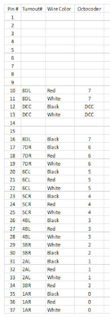
A Pin Designation Chart to help keep track of what wires go where. The turnouts are named (e.g. 1AR = 1st turnout, Block "A", Right turn) that coincide with their names with the Railroad & Co program. And where on the Octocoder the wires plug in to.:
And we got a cable! It's kind of messy, so....
Tucking the wires into this Split Wire Loom should make it all neat.
Under the layout shot. Success- It's in there! But the cable is only half of it. Now comes wiring the receptacle. The servo wires will radiate out from here to the turnouts as they are installed. A lot of work that will never be seen. But it will be felt. Each trolley navigating its own route should be very cool to see.
Yes sir!
Very cool to see.
Dandy


