Read the Free Trolleyville Times Monthly for the Latest News on Prototype and Model Traction!
Showing posts with label brasswork. Show all posts

Monday, December 05, 2022

#135 ~ Precision Instrument

 Trolley Poles and Hold Down Hooks

Fabricating some trolley pole hold down hooks.

Last time I already installed the trolley pole bushings but then I goofed and installed the weights before installing the trolley pole hold down hooks.  

But looking at the prototype hold down hooks, I may have not goofed at all! I think I can work with this.

For the Trolley Poles I used Miniatures by Eric Traditional Trolley Poles HTP4.

The hold down hooks are fabricated using some .015x.042 Brass Flat Bar from Detail Associates.

The hold down hooks need to be at a height so that the trolley poles are horizontal when in the stowed position.

The .015x.042 brass bars slipped between the roof and running boards nice and snug.  A little epoxy will hold them in place.

I think I got the angle just right!  I painted the hold down hooks black and glued them in.

Ooh! Nice!  #135 is looking like the precision instrument that its meant to be!

Yes sir!
The precision instrument its meant to be!

Dandy

Monday, September 12, 2022

#135 ~ Silver Gates

 Modeling Gates For the Class 1 Cars

Considering different materials to simulate the chain link construction.


Invented in the mid 19th century and brought to the United States in the 1890's, I suspect that chain-link fencing may still have had a novel quality about it when these cars where built, before becoming somewhat of a blight on the landscape by the mid 20th century.


I had some Precision Scale Brass Screen left over from previous projects so I decided to use that.

I cut the screen to size and then painted it silver.

And glued it to the car. I tried using CA (super glue) but found it too difficult. I settled on using white glue. That gave me plenty of time to position it before it dries and gives me the opportunity to remove it later.

But I'm not real pleased by how dense the screens look. It should have a more of a see-through quality about it.
So I might try something else.


Several different model manufactures offer screen material in various size meshes for modeling. Somehow I would need to determine the mesh size needed. Clover House lists scale conversions for their mesh sizes. Available in brass or nylon.

Another inexpensive option is Tulle from fabric stores. Tulle comes in a wide variety of sizes and materials.

I think I'll leave it as is for now and reevaluate when the construction of the car is complete.  If it still bugs me I'll swap out the gates with one of these other materials.

Yes sir! If it still bugs me!

Dandy


Monday, June 29, 2020

№ 9 ~ Going for a Drive

A NWSL Stanton Drive that is.

     In a previous post I had mentioned that motoring this trolley would be the stumbling block for this project. But a Dan D. Sparks Blogspot reader Don Ball had commented that he has had luck with the  NWSL’s new DCC-ready, self-contained underfloor power unit. So after looking in to it I've decided to order one and give it a go.

A quick look, it looks like it should fit (somehow):

Specs:
H.O. Scale NWSL Stanton Drive Model 1215
8'0" Wheelbase
33"/110 Wheels

The 33" wheels are the smallest that NWSL offer. The original wheels on the model are 28". So I had to give a little there.
I also went with the 110 wheel width. Four wheel cars notoriously ride rough, model or prototype. So the wider wheel width should help the car successfully navigate the intersection every time.


Just barely fits! Couldn't be any bigger. The corners of the Stanton almost touch the four screws holding on the side frames. If it was any bigger I would have had to find a different way of attaching the side frames.

The original floor had to be opened a bit to fit the Stanton. I was able to keep the original weight in place. A motor mount was fabricated for the Stanton to screw onto and hold it at the proper height.

An important thing to note is that the Stanton is not symmetrical in length. The housing was designed for two different wheel base sizes (probably 8'0" and 8'6" in this case). I have the smaller size so one of the wheel sets is closer to the pivot than the other. So Note to Self: The motor mounts one way (wires opposite side of pivot from the weight).

It's in there! What was once a formidable task is now in the past. Relief. Now it's time to move forward. Next: Decoder and a Pole.

Yes Sir! Keep moving forward!

Dandy

Monday, May 04, 2020

LMB Old Time Trolley

Sizing up an Old Model to Rebuild into SDERy #9

Last post I determined which cars I'm going to use for my fleet. But as I was retrieving them from my collection I came across this old Old Time Trolley "basketcase" model I purchased from George Jones. My first thought was to try out some Tru-Color Reefer Yellow on it to see if its a good color to represent SDERy Mission Yellow. But the more I look at this car...

 
I believe this is be an old LMB "Open End Trolley" model from c1961.

The model is very similar in appearance to SDERy #9 and #10.

Built by Brill in 1892, #9 and #10 ran for 17 years before they were retired in 1909.


A side-by-side comparison reveals that the windows on the model are too short as well as is the roof. Other than that though its pretty darn close.  I think that the model captures the feeling of the prototype quite well.

So into the Pine-Sol bath it went to strip it of paint.

I also fabricated route signs for the sides of the roof.

I guess I'm moving forward with this project! But I'm not sure how far I'm going to be able to get with it, motoring this model seems to be a stumbling point. But so far I'm committed to painting and decaling it. After that, we'll see where this goes

Yes Sir! We'll see where this goes!

Dandy


Monday, February 24, 2014

Armature Nite

Building the Skeletal Framework for the Streetlamp that will Act as a Conduit for Wiring and Support the LEDs AND Trolley Overhead! Crazy Project I Know...

Built of brass, this armature performs three functions. 1. Support the LEDs so that the streetlamp will light up. 2. The brass tube is a conduit for the positive wires and the brass itself is the ground. 3. The loop at the top of this assembly is a tie off for the trolley span wires. Then this armature will be placed in a rubber mold and resin will be poured around it creating an ornate streetlamp! That's the plan anyway. Yes sir- that's the plan!

The basis for the armature is a 3/32" brass tube. A brass rod that has been drilled to accept a brass wire loop soldered on, is inserted into the tube just above where the holes for the wires are drilled.

The negative lead of the LED is bent and soldered to the brass. The positive lead is trimmed short and a thin wire is soldered on and then threaded down the tube which will protrude under the layout where the resister and electrical hookups reside. 


Okay! Now this next part turned out to be way too much work and is actually unnecessary! But I'll post it anyway for your edification and entertainment.


The resin will cover the bulbs so I milled lamp globes out of acrylic tube to fill in the space in the rubber mold.

The acrylic tube fits over the LED perfectly. An Acrylic rod is inserted in the top of the tube to fill in above the LED where the fancy curves of the lamp globe will be carved in.

 Using my Dremel Tool as a lathe. I have a chuck the fits snug inside the acrylic tube and the teeth bite in holding the lamp globe firmly.

Then spinning the acrylic a small file shaves it into shape.

Before and after.

Wholly Katz! Its lit! It works! This thing is actually working so far! This project might actually pan out after all.

Alright! Well! This is how the armature fits in the mold. Next week I'll pour the resin and we'll see if we get a respectable looking streetlamp. Yes sir! We'll see if we get a respectable looking streetlamp out of all this!

Dandy


Monday, February 03, 2014

Boulevard Streetlamp / Line Poles

Attempting To Build A Working Combination Streetlamp / Linepole!

 Well here it is, a fresh 3D print from i.Materialize. But this is only the beginning. This print can't be used on the layout because one: I believe the "Prime Gray" material would be too brittle for the tensions of the overhead, and two: I want these lamps to light up. So this fella will be the "master". A rubber mold will be made from this print that all the other lamps will be cast from. But I digress...

As detailed in a previous post, each of the 6 streets feature distinct line poles. The 1920s era street pictured above is to have Boulevard streetlamps that double as line poles. Right now I have temporary wooden poles that are planted beyond the sidewalks until the streetlamp locations and hole size to be drilled in the sidewalks are determined. But for now, the temp poles are fouling where the building are going to be placed. So these lamps have become the priority project.

 San Diego didn't have these kind of poles but our neighbor to the North was kind of fond of them. The Pacific Electric sported these kind of poles in a few cities. This one was in Long Beach.

The San Diego Electric Railway attached their overhead directly to the adjacent buildings, thus clearing the streets of unsightly linepoles. But I don't want to attempt to deal with attaching the overhead of my layout to model buildings. So I thought I would try modeling these Boulevard Lamp Post / Line Poles (I really wish I knew what these were called!) instead. Besides, they look cool! 

Years ago I fabricated a couple of these lampposts out of brass. But they were very difficult to build and highly time consuming. There are so many small parts that trying to solder one part melts the joints of the other parts. Frustrating. So the project languished until either my soldering skills improved, or I thought of a better way of building these, or some sort of miracle happened.


Well wouldn't you know? A miracle happened! In the form of 3D Printing! Building this lamp with a 3D program is WAY easier than building it with brass. And a lot faster. I modeled this with 3DS Max.

My lamp design is a hybrid of San Diego style Boulevard steetlamps and the Los Angeles linepole streetlamps.

I'm pleased with how the print turned out. The lamp had to be designed with the 1mm minimum thicknesses required for 3D Printing. But I believe the level of detail is just right for HO scale.

Now comes making a silicone mold from this lamp. This will be a new adventure for me. Yes sir! This will be a new adventure!

Dandy

Monday, August 19, 2013

The Line Pole Polka

Helping to give each street its own personality by using different styles of line poles.
This layout is very rotationally symmetrical (to the order of four!) and features six streets. In an attempt to prevent every street from looking the same so as to give the impression that the street cars are actually going somewhere, each streets "hardware", such as street lamps, telephone poles (or lack of), greenery (or lack of), signage, building architecture, and this case, line poles, are going to be of a different design.

The biggest factor in deciding the style of a pole is the era that its street represents. Refresher: each street represents a different decade, from the 1890s to the 1940s. So here are the styles I have selected for each of the six streets.


1890's

Studying old time photos reveal that the earliest line poles were of square milled lumber construction. A lot of times telephone poles doubled as line poles. These poles feature fancy iron work so as to illustrate to the citizens that this is a first class trolley operation that is here to stay and is worthy of your investment and patronage.


But because of the regular spacing of telephone poles and my need for more poles to support the overhead, I added some bracket poles to this street. All the poles on my layout are of brass construction, distressed and painted to look like wood or steel.

1900's

By the ragtime naughty "aughts", ornate was on its way out and simpler geometric forms were becoming vogue. This pole reflects that style.

1910's

Traction companies started switching to steel poles for the same reason rolling stock construction utilized less and less wood and more and more steel, it was more durable and lasted longer. These poles take advantage of K&S Engineering's telescoping ability of their brass tubes. Just don't get the soft stuff! Painted with (the now defunct) Floquil Light Green and weathered with Bragdon Weathering powders.


1920's
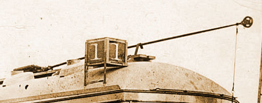
 Cities reacted to the fact that the new century turned their streets into a jumble of power, telephone, and trolley wires. Downtown San Diego eliminated telephone and line poles and attached the span wires directly onto the adjacent buildings. Telephone and power lines were buried in the streets, thus clearing the streets and giving a cleaner look. Attaching span wires to my model buildings presents some challenges I'd rather not delve into. So...

 A rather nifty alternative are these double arm boulevard lamps with a trolley linepole extension as seen here in Long Beach, CA. Streetlamps in HO scale have a big problem with being way overscale in order to get them to light. So it looks like I'm going to have to build these myself. A project all in itself!
 
After fabricating this one from brass, it has become clear that to build the 12 required for the layout would be way too time consuming. 3D printing is an option but the poles would need to be durable enough to stand up to the constant tension of the span wire. Right now I'm favoring the idea of doing a 3D print of a master, and make a rubber mold from it. Then during the casting process, place a brass rod in the mold, add the LED lights, tucking in the wires, and then pour the resin around it all. That might work, right? Yes sir! That might work! Until then, temporary wood dowels are being used as place holders for these lamps on the layout.

1930's

Economic Depression. Automobiles taking an awful toll on ridership. An inexpensive, standard wooden bracket pole will suffice.

1940's

These poles are patterned after a double bracket pole that was common when linepoles were placed down the center of the street. San Diego favored these kind of poles outside of Downtown. Since the other side of my street isn't there, the other bracket is only present in the abyss!

 So there you have it! I hope you like. I've tried making these linepoles every bit of an interesting model as the streetcars. Yes sir! Every bit of an interesting model as the streetcars!

Dandy


Monday, April 15, 2013

Simple, Stately, Line Poles

Getting very anxious to get the layout running again, I have fabricated a whole new batch of line poles.

Having the streets right on the edge of the layout means that the other sidewalk isn't there to plant the second span pole.  So my poles were originally built with these bracket arms:

But the tension of the overhead proved to be too great for the poles on the street corners and these bracket arms had a tendency to suddenly bend 90 degrees, ruining the pole. So I have decided to bite the bullet and add span poles along the edge of the layout.

These square milled line poles were very common pre-20th century.  Eventually they figured out that milled poles were more expensive to build and that un-milled poles are actually much stronger. So they fell out of favor fast and seem to be all but completely gone by the 1920s. I think that these square poles are actually quite handsome, you know, for a pole. So my 1890s and 1900s streets will sport these nifty poles.

 I fabricated my poles from solid 1/8" square brass stock. After I had painted and weathered them, I was won over by the Southern California Traction clubs practice of adding "eye-bolts" to their poles. Should my permanently attached span wire bend or break, I would be faced with some major repair. But seeing the ease at which the SCTC could swap out their span wire with this "eye bolt" method, well its obvious which method is superior. Yes sir, its obvious.

SCTC member, John McWhirter, posted a sketch on a Yahoo traction modeling group that depicts an effective method of adding "eye bolts" to line poles that I followed to fabricate my own. Basically its looping span wire around a track nail and then threading the ends thru a hole drilled thru the pole. The ends are bent to hold it in place for soldering. Then trimmed flush.

Here are my poles with their new eye-bolts installed. The soldering ruined the paint job near the bolts so I have some touching up to do before the poles can be installed on the layout.

Here is the first pole to be installed on the layout. Notice that the new eye-bolt isn't overly huge and helps the pole maintain its simple, stately elegance, you know, for a line pole. Yes sir! Simple, stately elegance, for a line pole!

Dandy