Read the Free Trolleyville Times Monthly for the Latest News on Prototype and Model Traction!

Monday, April 21, 2025

#135 ~ Decodering

Installing, Wiring, and Programing a TCS KAM4-LED Decoder.

Train Control Systems Keep Alive Decoder for LEDs.


Hot Glued the decoder to the ceiling right in the center of the car.

The wiring is pretty straight forward except that the Red wires are attached to the trolley pole bases and the Black wires to all wheels:

Red = Trolley Poles
Black = Wheels
Orange = Motor
Grey = Motor
Blue = Lighting Power Bus (positive (+) ).
White = Headlight (-)
Yellow = Rear Headlight (-)
Green = Forward Interior Lights (-)
Purple = Rear Interior Lights (-)


Programing

With the Digitrax Zephyr


Programing the new address to #135:

1. Place car on the programing track.
2. Press 'Program Mode' on the Zephyr. until display reads as 'dir'.
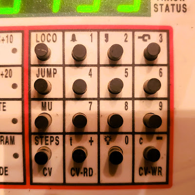
3. Press 'LOCO' button. Display reads 'Ad2' for addresses 1-127, press again to display 'Ad4' for addresses 128-9999.
4. Press '1' and '3' and '5'. Display will read '0135'.
5. Press 'CV-WR'. Display will blink the 'Ad#' and then '0135'.
6. Return the car to the mainline to test it.


Some CV's need to be changed.  The Green wire (forward interior lights) defaults to the Function 1 (F1) button which is fine. But the Purple wire (rear interior lights) defaults to the F2 button which is a momentary contact button normally used for locomotive whistles (the whistle sounds when the button is held down). Which means that the interior lights on car #135 only light when the button is held down. So the purple wire needs to be remapped to the F3 button instead.

Digitrax Zephyr Function buttons. 
I need to remap the Green wire (CV 35) from function button 2 (F2) to function button 3 (F3).

Even though these trolley cars are bi-directional I have designated the open section as the forward end of the car to simplify things (the open section is easier to see into so I want to put my motorman figure in that end). 

Green wire (CV 35) = Front                Purple wire (CV 36) = Rear.


To remap the button-

Program:     CV 35 V=4  (simply confirm this value since this is the default)
                      CV 36 V=16 (from the default value of 8)


Remapping CV's is easiest using JMRI Decoder Pro

Otherwise its button mashing on the Zephyr:

1. Place car on the programing track.
2. Activate 'Program Mode' on the Zephyr. Program Mode light lights up.
3. Press the 'CV' button. Display reads 'ad2' or 'ad4'.
4. Press '3' and '6'. Display reads '0036'.
5. Press the 'CV' button again. Display still reads '0036'.
6. Press '1' and '6'. Display reads the value of '0016'.
7. Press the 'CV-WR' button. Display should blink once as it writes to the decoder.
8. Return the car to the mainline to test it.

And that ought to do it!

Yes sir!
That oughta do it!

Dandy


Monday, April 07, 2025

#135 ~ Illumination

 Headlights

Installing LEDs for the headlights.

Working headlights on streetcar models I find to be most helpful when working with DCC.  When I place the car on the track the first thing I do is hit the headlight button on the command station to determine if the car is getting power and responding to commands. If the car has been sitting on a siding for a while but the headlight is still on, then I know it hasn't ventured onto a dirty piece of track and the KeepAlive lost its power. So I always try to have working headlights on my cars.

The rounded lens of these LEDs look great as a headlight.

1.8mm, 3 volt, warm white LEDs works for this. The lens portion will fit inside the housing while the square portion glued against the inside wall.

Reaming out the housing a bit was required to accommodate the LED.

Perfect fit! Positive leads on top, negative on the bottom. But the square portion of the bulb is still a bulb, which means it will be casting light inside the car. So...

Black paint to block the light from the back of the LEDs, but keeping the lens clear.

Wire Routing. The leads to the LEDs are bent and trimmed so as to aid in routing the wires past the windows and up to the decoder that is mounted on the ceiling.


Illuminated.  I hooked it up to a battery to test it out and voila!

Yes sir!
Voila!

Dandy

Monday, June 24, 2024

Gassier Lamps

Brawa Historic Street Lamp.

Oh Sure! Now This Model Shows Up!

After committing and installing the gas lamps on 1890's street, this more accurate model shows up on eBay!  Isn't that always the way!

This Brawa model is much closer to the style of the gas lamps San Diego had in the early 20th century:

So I purchased it to see if it would be worth it to swap out my current gas lamps.
Well, it showed up in the mail and one thing became apparent to me right away...

It's HUGE!  The lamp in the vintage photo is about as tall as the streetcar. But this Brawa lamp is about a car and a half tall.  Despite claiming that it's HO scale on the box it might be better suited for O scale.  Hey- I wonder if it comes in N scale?

Yes... yes it does. But it looks to me like all they did was make the HO lamp shorter. The globe is still on the large size.

Well it all doesn't matter anyway, these lamps seem to have been out of production for quite some time now. Brawa doesn't make them anymore.  So I think I'll stick with what I have for now.  Maybe something will come along later. We've seen this sort of thing happen before, maybe it'll happen again?

Yes sir!
Maybe something will come along later!

Dandy

Monday, January 22, 2024

Modeling Streetlamps ~ It's a Gas, Gas, Gas!

Modeling Electrically Ignited Gas Lamps

When electricity came into use it wasn't used for illumination right away. Instead, electricity was used to ignite the gas lamps.


    This made sense since the infrastructure for gas was already there and worked perfectly fine. Electric ignitors was a logical upgrade to this system.

    Here are my 1890's street simulated gas lamps being ignited and then warming up to their operating temperature.  Pretty Neat-O! That would have been a site to see for real back in the day, yes?

Here is a Gas Lamp as they appeared in San Diego in 1905.


    The closest models that match the prototype I can find are these identical models by both Miniatronics and Viessmann.  Not quite right, but they do capture the flavor. But they are awfully pricey.  Occasionally I'll find one at a bargain price, so I'll pick it up.  Eventually I had the 6 that I needed but four of them have incandescent bulbs. I'm a fan of the long lasting LED's.  So my plan was to replace the incandescents with LEDs.  But I made an interesting discovery about that...

    While looking around at Gas Lamp models I stumbled across this Gas Lamp Ignition simulator module (Viessmann 5066).  And it will power both the incandescent and LED lamps. Well this sounds fun! So I purchased it.

    And installed it under the layout. It only has 5 ports so two of my 6 lamps with have to double up. I chose the two on the extreme ends so that it will be less noticeable that they are in sync.

    Nothing like wiring everything up properly just to have it fail. After going through all the trouble of trouble shooting I discovered that the wiring schematic that came with the 5066 Ignition module was incorrect. Where it showed the brown wires going to each of the 5 ports it should have been the yellow wires (as seen in the correct schematic above).  Nothing going smoothly is par for course for this hobby I guess.

I decided against the Viessmann power supply (5200). It's overkill for my needs. So instead I ordered this basic 15 volt power supply. 

The power connector was installed with double sided mounting tape with a cable clip to secure the wires.

Plug it in and voila!  Now this is where the difference between incandescent and LEDs can be seen.  Incandescent on the left and LED on the right. I'm a big proponent of LEDs but the incandescents are performing much better here.  The LED is way too bright and doesn't have the range of brightness that the incandescent has. The incandescent does a great job of igniting and then glowing dim before slowly brightening as it warms up. Its final operating brightness is more realistic as well.  Plus the pool of light cast by the incandescent on the building and streets is much more pleasant than that cast by the LEDs.  Instructions come with the lamps on how to change the lightbulbs, so I might do that at some point.

But for now I am quite satisfied.

Yes sir!

Quite satisfied!

Dandy

Monday, January 08, 2024

Jessop's Clock ~ Grand Finale

 Adding the Final Details

to this fantabulous Time Piece.

Voila!

Photos of the Jessop's plaques were straightened, scaled and duplicated in photoshop. There is no way I can model the clocks mechanism in the base of the clock, so it too will be represented with a photo. 
Then this was all printed onto photo paper with my home printer.

The back of the plaques were painted with the same copper paint as the rest of the clock.

And then applied to the clock. The edges and back were touched up with more copper paint in hopes to seal it all up and protect it from warpage.

And last but not least- the Eagle has landed!

Well whaddaya think?  Not a bad transformation, huh?

Yes sir! Not bad at all!

Dandy

Monday, January 01, 2024

Happy New Year!

 2024

Here's to a Productive Year!


Yes Sir!
A Productive New Year!

Dandy

Monday, December 25, 2023

Jessop's Street Clock ~ Painting

 Painting This Model Just Like Painting Any Other Model.

Testors Paint makes a nice Metallic Copper color. And its small bottles should be about right for a small project like this.


Here are the colors I'm trying to represent:

Copper. With Gold and Black trim.  On the left is the clock looking polished and shiny after being restored and installed at Horton Plaza.  After several years it has patinaed as seen on the right.

The modified Brawa model has been masked and is ready for the paint booth.

Primered.  The Testors "rattle can" primer works just fine for this. I applied two coats within 3 hours of each other and then let it dry for over 24 hours. Testors recommends 48 hours but the weather has been warm and dry so it should be fine.

Coppered. Wow! It looks like a brand new shiny penny. The paint was thinned 15 drops thinner and 20 drops paint for the airbrush. Two coats covered nicely. The second coat was airbrushed on within 3 hours after the first coat as recommended by Testors. 

Unmasked.  The suspense was killing me as to if the masks did their job. With the spraying done, now is the time for the unmasking.

Success!  For the most part the round masks worked. As expected a little touch up paint was required.
After letting the paint dry for the recommended 48 hours it was time for the...

Golded.  This was rather difficult to paint as the gold isn't showing up so well. It's very similar to the copper color. Hopefully another coat or two will help it pop?

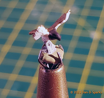
Birds turn.  I'm going to try something different with this bird. I'm going to dip him right into the gold paint bottle!  This could go very bad if I drop him in!

The claw pick up tool seems to have a good grip on him- so in he goes!

Golded Eagle.

Blacked.  It took me way too long to notice that the base is also black.  So I masked off the clock and airbrushed the base black.

Gold Bits.  Some of the details are impossible to model so they are represented with a dot of gold paint. This dot of paint comes way closer to the detail than anything I could model.

Painted. And thus completes the painting portion of this project.

Yes sir!
Painted!

Dandy.