Monday, October 10, 2011

Niles Project ~ Strategic Seating

Arranging seats around the motor so its not so conspicuous.

Additional seats are fabricated using the original seats as reference:

From Right to Left (above), the narrow brass bar stock is used for the seats and the wide bar stock for the base. The bar stock is measured, marked and cut. The wide bar stock is notched so that the tabs can be folded up as the seats legs. The wide center tab is ground off with a moto-tool. The narrow stock is bent matching the angle of the original seat backs. Then the seats and base are soldered together. Take care with soldering the seat assemblies to the floor. My seats are a tad too close to the sides and scrape when the body and floor come together.

Installed and painted. Some seats are right over the motor mounts. So seats were fabricated and then soldered to flat bar stock thick enough to get the seats to their proper height. Holes are drilled to accommodate the mounting screws for the motor. So what you see here is a sandwich of floor, mounting plate, insulation, motor tab, and then seats, all screwed together.


See? The motor is already disappearing into the background. If you look closely, the front seats of the center section (behind the figure) are seat backs only. You can see holes on the floor in front of them where the tabs on the bulkheads attach to the floor when the body and floor come together. Right where the seats are.
Alright, the seats are in and ready for paying passengers. Yes sir! Paying passengers!

Dandy
.

Monday, October 03, 2011

Niles Project ~ Gates

Passenger gates make for a nifty little detail to add to these models.

 These gates in the doorways are included on all the San Diego Niles cars, so my models shall be so equipped. And why not? They are easy enough to add because...

...Cal Scale offers "Tailgates" for passenger cars that should fit the bill here just fine. They are available in brass (left) of plastic (right). I bought both to see which I preferred but forgot to add the brass gates during the soldering of brass details stage of construction. Soldering after the fact will ruin the paint on the cars. So #105, #107, and #109 will get the plastic gates. #110 will get the brass gates since it hasn't been painted yet.


Even though the plastic gates are black, I painted them with Floquil Engine Black paint anyway. Black plastic always looks like black plastic. Floquil paints are dead flat and kill the shine beautifully. A little bit of weathering chalks will help bring out the detail again.


A tad bit over sized, the Cal Scale gates achieve the desired effect anyway. The gates are glued in with good 'ol Micro Kristal Kleer.
The Passengers have found there seats and Conductor Carl has closed the gates. Were ready to roll. Yes Sir! Were ready to roll!

Dandy

Thursday, September 22, 2011

5 Years and Still Going Strong!

Well... for the most part.

Welp! I've been making regular updates to this blog for 5 years now. And what do I have to show for it? Three superdetailed trolley models and $23.67 of ad revenue in an untouchable account. Hmmm... this must be one of them "labor of love" type of things.

This year was actually shaping up to be the most productive year for my modeling as well as blog posts. But this darned economy finally caught up to me and all but put a stop to my traction empire building. Seems that things like modeling have to take a back seat to making a living. Silly world we live in.


Surprisingly, its not so much the lack of funds that is the problem (though it is a big part) so much as it is the time factor. I don't have the time to model like I did when I was gainfully employed full time. I'm busier now than ever before. Go figure that one!

Now for what your really here for.... the stats!:
This blog entertained 3787 visitors these past 12 months. That works out to an average of 10.38 visitors per day.
The #1 page visited is my April Fools day photo trickery : My Old San Diego Trolley Layout. Followed by the much more useful post: Painting Brass Models. The Birney Project page rounds out the top three posts read.
And as I already mentioned, ad revenue is only $23.67. I wasn't expecting to get rich doing this, but I was hoping for some extra modeling funds. But 23 bucks in 5 years... I might do away with the ads. 


All right fellas, I have a streetcar model a year addiction to feed. So I got to hit the pavement and make some dough. Yes Sir! Gots to hit that pavement!

Dandy

Friday, August 26, 2011

San Diego 1912

San Diego 1912, by David Lyman. Mixed traditional media.
Yes Sir!

Dandy

Monday, August 08, 2011

Niles Project ~ Gurzelin'

Installing a Hollywood Foundry Gurzeler on Niles #105.
The Gurzeler is the second mechanism that I'm trying out on these Niles cars. #107 got the half floor which has worked out just fine. And now #105 will get the Gurzeler. Each mechanism has it advantages.

This is the city. Los Angeles, California. I belong to a club here. The Southern California Traction Club. I'm a traction modeler.
Sunday, 2011, a club member who goes by the name, interestingly enough, of Fred Gurzeler, approaches me. Fred, a man of a few words, reaches into his pocket and pulls out a small object. Its an etched plate. He hands it to me explaining that its a mounting plate for mounting the Gurzeler mechanism to Suydam PE 414 cars. No mention of where it came from, or what those mysterious markings mean. Just a well manufactured mounting plate. That's how Fred operates. Who am I to argue or ask questions? Its exactly what I need. Thanks Fred. I owe you one.

Exhibit A.
The mysterious Gurzeler mounting plate.

While soldering the mounting plate to the floor, I managed to unsolder one of the seats. And maybe some underbody details. No matter! Easily fixed.

I wasn't able to get the opening for the belt exactly centered because the plate has to fit between the interior bulkheads that the floor screws into. Even if I did, it later proved to be a problem. The opening needs to more towards one end or the other so that the motor is centered inside the car because the flywheel protruded into the interior bulkhead base. (Edit: Turns out that if I had ordered the Gurzeler Motor Package, I wouldn't have had this problem! DDS 10-11)

The Gurzeler is a simple yet brilliant design. The motor is mounted in place with double sided tape which also acts as a sound barrier. The belt (not an O ring, but an actual belt made to withstand the tension) replaces the noisy gear tower and also pulls down on the motor, helping to keep it in place.

Under floor view. I chose silicone tubes to transfer the power to the LowBoy trucks. Seems to me silicon tubes would be the easiest to replace should they fail after a while.

With no giant motors under the floor and those silicone drive shafts, these cars should be able to negotiate some crazy radius curves now!

This all went together easy-peasy (except for the off-centering of the motor. See below). The motor and silicone drive shafts are nice and level. I added a Miniatronics 2 pin Micro Mini Connector socket by soldering the leads to the motor and gluing the socket to the top of the motor. The other plug will connect to the decoder. This makes for a convenient way to separate the floor from the body for maintenance.

(Edit: Turns out that if I had ordered the Gurzeler Motor Package, I wouldn't have had this problem! DS 10-11) I had to cut a notch in the base of the bulkhead so that the flywheel on the motor will clear when attaching the floor to the model. For the folks who don't have their own mysterious Fred Gurzeler and have to fabricate their own mounting plate at home, the openings for the belt drive and screws need to be closer to the end of the mounting plate. We could all use a mysterious Fred Gurzeler in our lives, couldn't we? Yes sir! We could all use a mysterious Fred Gurzeler in our lives.

Its in there! The motor does sit slightly above window level. But models are very seldom viewed from this angle. All motors would be visible from regular viewing angles. So that's where populating the model comes in. Putting folks in the seats will take the attention away from the motor as was done with Birney #301. The only thing guests will notice about the motor after that is the smooth quiet operation of the model around the layout. Now if I could just get to building that layout. Yes sir! If I could just get to building that layout!!!

Dandy

Monday, June 27, 2011

Niles Project ~ Motorin'

Installing a Hollywood Foundry Half Floor Motor Mount and Level Shifting Gearbox on Niles #107.


Right out of the box the mechanism is a pretty good fit. This is going to work just fine.

The immediate problem that presents itself is that the mounting holes don't line up with anything to screw into. The second problem (that I wish I had taken a picture of) is that the gearbox is too low. The drive shaft to the truck is on an angle. And while that would still probably work, it seems to me a level drive shaft would be the most efficient and problem free.

Both issues are easily remedied in one fell swoop by soldering a length of 1/16" x 1/4" brass bar stock to the frame.

Fortunately I have the good folks at the Southern California Traction Club (and their drill press) to help me drill and tap the holes for the screws. The motor also came with a silicone mounting pad to absorb the noise. I cut it to size and placed it between the new brass bar and the half floor mount as seen in the photo above.

Between the new brass mounting pads and the silicone pads, they lifted the motor to just the right position for the drive shaft to the new LowBoy Trucks to be perfectly level. And the motor is still below window level. All thats left now is to transfer the sideframes from the old truck to the new truck and wire the motor to the decoder. Then this car will be ready for a spin around the test track. Yes sir! All ready for a spin around the test track!

Dandy

Monday, June 13, 2011

Niles Project ~ New Mechanisms for the Old Girls.


Looks like Hollywood Foundry has two mechanisms that will potentially fit the old Suydam Niles cars. The Half Floor Gearbox or the Gurzeler, both used in conjunction with the BullAnt LoBoy Trucks.

Both mechanisms have their advantages and disadvantages of course, but really, the disadvantages are very minor. So either mechanism should work just fine for these models. Therefore I have ordered one of each to try them both out.

Also worthy of note, I'm very impressed with the Hollywood Foundry's new Diablo mechanism. The Diablo could be used with these cars, but not without some major modification to the interior bulkheads that separate the enclosed center and the open ends. If your okay with hacking away at these bulkheads then the Diablo might be a good choice. But I'm not so much, so I won't (But I am excited by the possibility of using the Diablo to remotor my Pacific Traction, San Diego 400 series, class 5 cars in the very near future!).

LinkAccording to my calculations, the 10 Series Half Floor Gearbox with a 1024 Motor will fit below window level of the car, maintaining that realistic see-through look (unlike Birney 301 which has a big ol' motor blocking the windows). The only downside is that the gearbox is a little noisy. I only say that because we are spoiled these days. The Gurzeler is very quiet and the Diablo is practically silent. The Half Floor Gearbox is noisy only in comparison to these. But really, its not all that bad!

The Gurzeler (also with a 1024 motor for consistency) will sit slightly above the bottom of the windows, but not by much. But instead of a gearbox, the Gurzeler uses a belt drive (with a real belt, not an O ring!). Therefore, as I mentioned before, this mechanism is very quiet.

#105 will be fitted with the Gurzeler and #107 with the Half Floor. After living with these for a while, I will decide which mechanisms to use for #109 and #110.

All the cars will be fitted with Hollywood Foundry's LoBoy Trucks. From what I understand, Geoff Baxter (of Hollywood Foundry fame) designed these trucks to directly replace the old Suydam trucks that had a bad habit of splitting their plastic gears, rendering them all but useless. Kudos to Mr. Baxter for this. Because of his efforts, these 40 year old Suydam cars can be built into fine models that can finally perform every bit as good as they look. Cheers to Mr. Baxter. Yes sir! Cheers Mr. Baxter!


Dandy


Monday, May 30, 2011

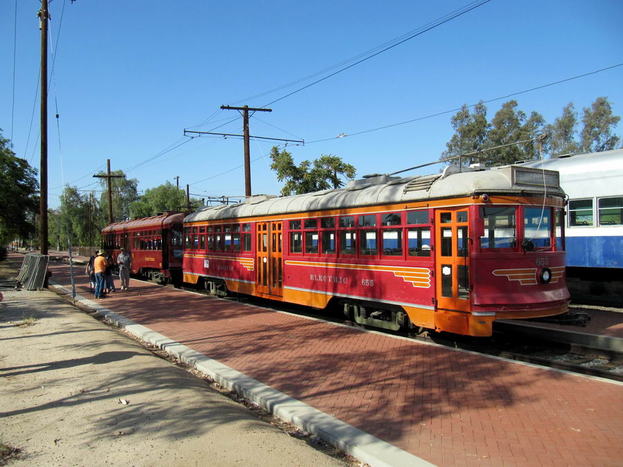
Pacific Electric Red Cars Weekend

This Fathers Day weekend! June 18 & 19th at the Orange Empire Railway Museum in Perris, California.


Two of my Niles cars (#105 & #107) will be on the Southern California Traction Clubs layout in the OERM's Town Hall. So stop by and say "howdy".


From the OERM website:

Join Dad for ride into the past on the Big Red Cars of the Pacific Electric. Although we operate selected PE cars throughout the year, this is the weekend when we have the largest group of them out to ride and photograph. Once again this year we'll also have the Southern California Traction Club on hand with their giant HO Scale model trolley layout.
On Sunday we'll also have a family barbeque from Noon-2 pm. Admission to the grounds is free, regular prices apply for train ride tickets ($12 adults, $8 children 5-11).

I'll be there all weekend and you should too. Yes sir! You should be there too!
Dandy

Monday, May 23, 2011

To Trolley Pole Reverse Or Not To Trolley Pole Reverse.

That is the question.
Exploring the two methods of wiring a trolley. The "cool" method or the more practical method.

(NOTE: This post was written when when the layouts were wired for standard DC (Direct Current). But with the advent of DCC (Digital Command Control) Trolley Pole Reverse is no longer an issue. Cars are wired for "Trolley Pole Forward" as shown below. -Dandy 2020)

The question we get the most when the Southern California Traction Club displays its modules is "are the trolleys getting their power from the wires?". Not only are the guests pleased when we inform them that indeed they are, but we will also do a little demonstration of "Trolley Pole Reverse" that guests take a delight in. It doesn't take long for a trolley to come by. So I'll put my finger lightly under the overhead wire so that as the car comes by, the pole will disengage the wire and the car will roll to a stop. I'll stow that pole under the hold down hook and explain that "one pole is wired to one pole of the motor, and the other pole is wired to the other pole of the motor". Lifting the opposite pole to the wire, the car jumps to life and continues on its way ~ in the opposite direction. Guests are thoroughly impressed.


But lately we at the club have been discussing reliability. As all model railroaders know, the toughest electrical continuity to maintain is the contact between rail and wheel. The slightest obstruction will cause a stall. Stalls are no fun. With traction modeling not only is that problem made double with the tiny contact between the trolley shoe and overhead wire but triple so with the just as critical contact between the stowed pole and the hold down hook.

When a car stalls, its usually the tiny connection between the trolley shoe and overhead that's been compromised. A gentle tap of the overhead is usually enough to reengage to shoe to the wire. If that doesn't work then its probably the wheels, nudging the car forward a tad should fix that. If that doesn't work then a wiggle to the front pole might invigorate that contact. If that doesn't work... well, you get the idea. It gets a little frustrating. So eliminating weak spots like these just makes things run a little smoother. But eliminating the contact between the rails and overhead isn't feasible. But that connection between pole and hold down hook can be addressed.


With Trolley Pole Reverse, one trolley pole is wired to one pole of the motor while the other trolley pole is wired to the other pole of the motor. Whichever pole is in contact with the overhead will supply the positive charge to the motor. The other pole is in contact with the hold down hook completing the circuit by providing ground. This method requires good spring tension to press the pole up against the hold down hook and a clean connection between the pole and hold down hook. A little contact cleaner fluid is helpful here as well.


Though I've never heard it called this, I'm calling this method "Trolley Pole Forward", as opposed to Trolley Pole Reverse. This method eliminates the contact between the pole and hold down hook, providing a bit more reliable operation. This is particularly useful in a DCC environment where a car can be reversed without reversing the polarity of the rails and overhead. We simply tell the decoder to run the car the other way.

I think it all comes down to preference. On a point to point operation, Trolley Pole Reverse might work best. For a "roundy roundy" operation, Trolley Pole Forward might be preferred. On a DC layout, I think Reverse could be the way to go. On a DCC layout, Forward could be it. I don't know. But I think once my layout gets rolling, time will tell which I prefer. Yes sir! Time will tell!

Dandy

(Edit- Time has told! Yes- on a DC layout, "Reverse" is a good way to go. On a DCC layout "Forward" is the way to go. -Dandy 2020.)

Monday, May 16, 2011

Real Men of Genius ~ Mr. Miniature Train Modeler

Congratulations to all of us model railroaders. We have finally have been recognized for our true genius:


MR. MINIATURE TRAIN MODELER

Bud Light Presents Real Men of Genius
(Real Men of Genius)

Today we salute you, Mr. Miniature Train Modeler.
(Mr. Miniature Train Modeler)
Yours is a perfect magical world wedged neatly between your furnace and your hot water heater
(Keep on dreaming)
Your mini town has a mini ice cream store complete with a mini soda jerk guaranteeing there will always be at least two jerks in your mini world.
(You'll never be alone)
Woo-woo, all aboard? First stop, Nutsville.
(Chug-chug, woo-woo)
So crack open an ice cold Bud Light, Master of your mini world, you're koo-koo about choo-choo's and that's fine by us.
(Mr. Miniature Train Modeler)


Kind of makes it all worth while, doesn't it? This Bud is for you. Yes sir! This Buds for you!

Cheers
Dandy

Monday, May 09, 2011

Niles Project ~ Brainz

The TCS M4 Decoder

The TCS M1 decoder is doing an outstanding job on the Birney car. So naturally I would use it with the Niles. But I have all those interior lights whose total milliamps exceed the limits of the interior lighting function of the M1. So...

It was determined that with the M4 (four function) decoder, the interior lights can be split between two functions. That way, the total milliamps of half the lights are within the limits of one of the functions. And the total milliamps of the other half are within the second function. So the M4 is what I ordered. And the M4 is what I got. I named it "Abby someone... Abby Normal".

LinkSo come on up to the lab and see what's on the slab. Then we'll install its braaaaainz. Yes sir! Install its brrraaaainz!

Dandy

Niles Project ~ Running Cost Tally

Model Railroading can get expensive. I'm going to try to keep a running tally of how much it costs me to rebuild these Niles cars. But don't blame me if I don't follow through with this. I mean, how do I factor in the use of Butane used for soldering? Or the use of tools (including Photoshop for designing decals)? And labor isn’t being factored in at all. etc.

Suydam PE 414 & 1300 Niles Cars Rebuild Cost Tally


#105
SD&SE
combine

#107
SD&SE

#109
Point Loma RR

#110
Sightseeing

Original Car Purchase 1

$250.00

$250,00

$250.00

$250.00


n/a

$3.50

$3.50

n/a


$0.66


$5.77

$5.77

$5.77


$0.42
 $0.42
TCS M4 Decoder $41.80

$41.80

$0.00
$0.00

Total

$298.65

$301.49

$259.27

$250.00

Notes:
1. Today's (2009) going rate for these cars (some were purchased for more, some were purchased for less, but they averaged out to today's going rate).
2.$2.50 ÷ 6 cars= $0.42

Ka-ching! Ka-ching! Ka-ching! Yes sir! Ka-ching! Ka-ching! Ka-ching!

Dandy

Monday, May 02, 2011

Niles Project ~ Resistification

Because LED's are diodes and don't behave like a resistor, a current limiting resistor is needed to prevent the current from exceeding the operating limits of the LED's.

Determining the size of resistor to use was simple enough. John McWhirter and I soldered the 4 LED's together in series. Then we attached a best guess resistor in series with them. Then we gave the circuit "the juice". 15 volts DC. We then carefully considered the results. If the lights were too bright for what I wanted, we would then replace the resistor with a" stronger" one. If the lights were too dim, then we replaced the resistor with a "lighter" one.

Actually, it was easier than I'm letting on because John has built a box with an array of resistors in it. A rotary switch switches from one resistor to another. So all we had to do really was connect our LED assembly to it and with a simple flip of the switch, find the the setting that gave me the illumination I was looking for.

Eventually we determined that a 1000 Ohm resistor (brown, black, red, gold bands) provided the right amount of juice to the 4 LED's to achieve reasonable illumination for the interior compartments of the trolley.

For the one headlight, we determined that a 15000 Ohm resistor works best (brown, green, orange, gold bands).


My next objective was to determine the most unobtrusive location to mount the resistors. I can't mount the resistors on the circuit board because they would interfere with the ability of the circuit boards to slip between the bulkheads and the ceiling. It would also be nice if the resistors weren't someplace visible through the windows. So this is where I got clever...

I need a jumper from the blue wire (lighting positive common) bus on the bottom of the circuit board to the LED leads on top of the circuit board. So why not have the resistor fill that bill? The leads to the resistors were bent so that one lead solders on top and the other lead solders on the bottom with the resistor itself on the front edge of the circuit board. Works for me. Yes sir! Works for me just fine!

Dandy