Read the Free Trolleyville Times Monthly for the Latest News on Prototype and Model Traction!

Monday, December 21, 2020

Mirror Test

Taking photos under the overhead wires by using a mirror.

     Cameras are too big to be able to take photos from a scale persons height. So I had the idea of placing a mirror on the layout at a 45 degree angle and aiming the camera down at the mirror that I wanted to try out:

You can actually make out the bottom edge of the mirror in this photo. And since the photo was taken in a mirror, I had to flip it in a photo editing app.

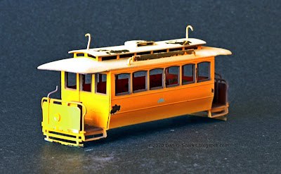
    It kinda worked! I was able to get a very low POV. Not bad for a quick and dirty test. The photo is a little 'foggy', I suspect that's due to my little mirror being rather old. There is also some ghosting effects going on that is quite prominent on the forward pole of the trolley. This is due to my little mirror being a 'regular' (second surface) mirror.

The mirror set up.

    For this photo of my mirror set up, my camera was sitting on the layout. This is the lowest I can get my lens to the ground and still we are about at the roof level of the trolley looking downward. So this mirror technique seems to be viable.

    I'm encouraged by these results. So I'll order a new 'first surface' mirror that should be more clear and eliminate ghosting, and continue to experiment.

Yes sir! Continue to experiment!

Dandy

Monday, December 07, 2020

Observations Regarding the Window Functionality on the SDERy Class 5, 400 Series Cars.

Random open windows on streetcars make for a nice touch on models, and while studying the windows on the SDERy 400's I discovered something rather interesting about how they function. 

(and I mean "interesting" as far as windows functionality could be interesting).


On the builders photo I noticed that the 3rd, 6th, 7th, and 10th transom windows are either frosted or opaque. But that's not all...

...they appear to be the only transom windows that are able to open (by tilting in) on these cars.

 
The transom window arrangement is surprisingly evident on this congery of 400s out for a stroll on Broadway.

    Because these transom windows were able to be opened it appears that the regular windows below them were fixed in the closed position.


    This interior view of a 400 reveal that the transom windows in question (3rd, 6th, 7th, and 10th) have the pull shades mounted on the lower window while all the remaining windows have full length window shades that could cover both the transom and regular windows.

    Then it appears that sometime during the SDERy's transition to the green and cream color scheme (1931) , the transom windows became permanently closed and all the lower windows were able to slide up. In this photo the 3rd, 6th, 7th and 10th lower windows are all open. The open windows on the front of the car was typical with many streetcars of that era which allowed for a nice breeze to blow through while the car was in motion (an early form of "air conditioning").


    So armed with this knowledge of how the windows work on the 400's, I "opened" some windows on my model by filing away the lower sash and soldering in a new strip of brass higher up the window opening. I decided not to try modeling the tilted transom windows as it seems to be even more tedious than what I've already done. Though I might be able to represent it by simply bending back the clear styrene when it comes time to add the widow glaze after the car is painted. Otherwise, this window stuff is rather useless knowledge (am I, and now you, the only ones in the whole wide world to know this?).

Yes sir! Rather useless knowledge!

Dandy

Monday, November 23, 2020

Boulevard of Electric Dreams

Finally!  All 12 Electroliers are placed and wired.

After pouring a new rubber mold I concentrated on casting the remaining lamps once and for all.

Electrolier combination streetlamp/trolley line poles stand sentry on Grand Ave.
This whole scene is lit entirely by the Electroliers.


The remaining 8 Electroliers freshly cast and receiving their silver paint.

    For power supply I ordered this regulated 3 volt 2 amp transformer from Evan Designs. Its regulated so as to prevent voltage surges blowing out the LEDs (the LEDs are cast into the lamp, there is no changing them out!). The output voltage is exactly 3 volts and the 2 amps mean I can power up to 100 LEDs. That should be enough power for the streetlamps on all the streets. It also included a wired socket that I mounted underneath the layout for the power supply to plug into.


    All that remains to do now is install the span wires between the Electroliers to support the trolley wires. But the fact that the 3 volt dc lamps and 13.8 volts ac DCC both ground to the poles is of great concern for me. It would have worked fine when track power was DC. But since I switched to DCC which is AC, I'm not so sure. The last thing I want is a Boulevard of Broken Bulbs! So i'm going to rig up a test lamp/pole situation to try it out first so as to try to preserve this Boulevard of Electric Dreams.

Yes sir! This Boulevard of Electric Dreams!

Dandy

Monday, November 09, 2020

Layout Automation ~ JMRI

The Computer Successfully Ran the Layout!

Java Model Railroad Interface is a free, open source program that works great for programing decoders, allowing the layout to be operated from a computer,  and even automating signals and other layout operation.


Last time, I installed a couple of Digitrax BDL168 occupancy detectors. Now I need to determine if they are in fact detecting. 

I'll use Loop A to test everything out. The cars can go 'round and 'round and I should get a good idea of how the program works and what to expect for the rest of the layout.

A Digitrax PR3 connects the command station to the computer:


After connecting the computer and all of the components together, I installed JMRI onto my computer. Then I drew a diagram of Loop A with its 8 electrical blocks, and assigned the proper BDL168 detection addresses to each block. Then I ran three cars on the loop to see what happens:

And it works! As you can see above the occupied blocks are red. The signal behind it turns red. When the car exits the block the signal turns yellow. When the car is two blocks away the signal turns green.

In this video I'm controlling the arched roof car that starts on the upper left while JMRI controles the two deck roofed cars behind it. JMRI does a good job of keeping the cars separated. Starting at the 1:45 mark I bring my car to a stop and the other two cars stack up behind it. Then I start it up again. Pretty darn cool.


A lot of folks have done great things with JMRI and while I've had great success with it, after spending some serious hours tinkering with this program I've decided to invest in TrainController Railroad & Co software and give that a go instead. JMRI is a powerful and versatile program but the lack of documentation on how to use the program is the deal breaker for me. After watching some YouTubes about Traincontroller I'm quite excited about it and look forward trying it.

But the important thing here is- the layout is automationable! And that was the whole point of it in the first place!

Yes sir! Automationable!

Dandy 


Monday, October 26, 2020

BDL168's ~The Robots Are Taking Over Our Jobs!

 Transitioning the Layout to Automated Operation.


    There doesn't seem to be any definitive how-to's when it comes to automating a layout. So I'm just going to figure it out as I go.


The first logical step seems to be Block Occupancy Detection. So let's start with that.

     A couple of Digitrax BDL168 LocoNet Occupancy Detectors should work for this.  Fortunately the track on the layout is already divided into electrical blocks from its DC cab control days. Later the blocks were "tied together" electrically when the layout was converted to DCC. Now I will "untie" the blocks electrically so that each block could then be wired individually to the BDL168's.


The control panel  illustrates the location of the 32 detected blocks. Each block is labeled with a city block letter and sequence number. One BDL168 will detect 16 blocks, so two are required for this layout (How's that for a perfect fit!). The intersection itself is its own block and does not need to be detected.


Rather than trying to wire the BDL168 while it's mounted under the layout, I temporarily mounted its 44 pin connector to a spare piece of plywood and wired it right there on the workbench. The other end of the wires are connected to terminal strips where the wires from the electrical blocks will be connected.

The wires had to be pre-tinned and then hammered into the shape of the holes they slide into.


Looking up underneath the layout (tap to enlarge photo). The 44 pin connector is mounted on the underside of the tabletop and the terminal strips are mounted to a joist with wires from the blocks routing in to the bottom row. The black and white wires on the far right are 14vDC (Digitrax PS14) power supply. The green wire in the center of all those wires is "ground" from the command station and the black wire next to it is the LocoNet connection.  The BDL168 (green circuit board) is plugged in to the connector. LocoNet cables plug in at the far left, one to the command station and the other to the second BDL168. The rainbow ribbon cable is for RX4 Transponder detectors, which it turns out, are unnecessary since the computer keeps track of what cars are where, and, the decoders I'm using don't transpond! But I digress...


So I fired up the layout, some lights flashed on the BDL168's, and I ran some cars around as if nothing had changed. Which is good. It means power is going from the command station, through the BDL168's to all the blocks. But are the BDL168"s detecting? I won't know that until a computer interface is established so a computer program can read the LocoNet information.

So the next logical step seems to be establishing a computer interface with the layout.

Yes sir! Establish a computer interface!

Dandy

Thursday, October 01, 2020

The Real № 9 in Action

Old Photo of № 9 Making Its Way Down 5th Street.


or it could be #10, I can't make out a number. ca1890

But I can make out that I put the headlight in the wrong place. This photo shows it on the roof. I wish I had seen this photo sooner. Installing the headlight on the roof would have been so much easier!

Yes sir! It would have been so much easier!

Dandy

Monday, September 14, 2020

№ 9 ~ Guiding Light

 Adding Headlights

The prototype didn't have headlights but on models the headlights are a great way to determine if the car is communicating with the DCC command station without having to run the car out of the carhouse. And since this model has a headlight casting on it, I might as well add headlights.

I should have done this before I painted the car. But the decoder has all these features for directional headlights, so I might as well use them.


Tiny LEDs. I picked up these 1.8mm/2mm LEDs online. I had to trim the leads very short to get it to fit on the car. The body of the LED is painted black so that only the "bulb" lit up.


Black Blob. Soldering the wires to the short leads proved to be tricky. I burnt one LED attempting this. But using a needle nose pliers as a heat sink helped. Then I slathered the whole thing with Liquid Electrical Tape to prevent shorting.  Yes sir! "Slathered"!

Routing the wires from the LEDs down through holes drilled in the floor, superglued along the bottom of the floor, then routed up inside the car to where the decoder will be.

A blop of Micro Kristal Klear for the headlight lens.


"Happiness can be found
even in the darkest of times,
if one only remembers to
turn on the light."

Albus Dumbledore

Yes sir! Remember to turn on the light!

Dandy

Monday, August 31, 2020

№ 9 ~ Official Portrait

The San Diego Electric Railway opened with great fanfare on September 21st 1892!

But by the time № 9 stopped for its photo much of the fanfare had moved on leaving one official, two patrons, a motorman, and a conductor to pose with it.


San Diego Electric Railway № 9

This marks the first time I've photographed a completed scene on my layout. Finally! But the layout is far from complete.

Here's the set up. Pretty simple.

Some people model historic battle scenes, some people model fantastic sci-fi scenes, I model everyday life of old San Diego. What does that say about me? I don't know. But if you know, don't tell me- I don't want to know.


Yes Sir! I don't want to know.

Dandy

Monday, August 17, 2020

№ 9 ~ Cast and Crew

Painting Up Some Folks to Populate Ol' № 9.

The Usual Suspects

These pewter figures by Andrew C. Stadden are beautifully sculpted, highly detailed, and very much in scale and proportion. They don't come painted though, so I'm going to have to make my first foray into doing that.

I glued them to blocks of wood to help make the painting process easier. First I spray primed them and then painted them by hand. There are plenty of videos on YouTube about painting figures that I watched before I started so I would have a pretty good idea of what I was getting into. This guy did a live stream of painting a Preiser figure in real time that helped a lot.

I chose figures that came closest to looking like these guys in this 1892 photo. I thought I would photograph a "reenactment" of this scene with my models.

Yes Sir! A reenactment!

Dandy

Sunday, July 19, 2020

Good Oldie Moldie

A New Rubber Mold for the Electroliers.

The Electrolier/Line Pole Project is back on track with a new mold after the last mold failed.


This time I went with a more durable silicone rubber:

Smooth-On Mold Star. It only cost a couple bucks more but its supposed to produce a stronger mold. So we'll see.

So to recap, four useable lamps done when we last left off, and now 8 lamps to go.

Yes Sir! 8 to go!

Dandy

Monday, June 29, 2020

№ 9 ~ Going for a Drive

A NWSL Stanton Drive that is.

     In a previous post I had mentioned that motoring this trolley would be the stumbling block for this project. But a Dan D. Sparks Blogspot reader Don Ball had commented that he has had luck with the  NWSL’s new DCC-ready, self-contained underfloor power unit. So after looking in to it I've decided to order one and give it a go.

A quick look, it looks like it should fit (somehow):

Specs:
H.O. Scale NWSL Stanton Drive Model 1215
8'0" Wheelbase
33"/110 Wheels

The 33" wheels are the smallest that NWSL offer. The original wheels on the model are 28". So I had to give a little there.
I also went with the 110 wheel width. Four wheel cars notoriously ride rough, model or prototype. So the wider wheel width should help the car successfully navigate the intersection every time.


Just barely fits! Couldn't be any bigger. The corners of the Stanton almost touch the four screws holding on the side frames. If it was any bigger I would have had to find a different way of attaching the side frames.

The original floor had to be opened a bit to fit the Stanton. I was able to keep the original weight in place. A motor mount was fabricated for the Stanton to screw onto and hold it at the proper height.

An important thing to note is that the Stanton is not symmetrical in length. The housing was designed for two different wheel base sizes (probably 8'0" and 8'6" in this case). I have the smaller size so one of the wheel sets is closer to the pivot than the other. So Note to Self: The motor mounts one way (wires opposite side of pivot from the weight).

It's in there! What was once a formidable task is now in the past. Relief. Now it's time to move forward. Next: Decoder and a Pole.

Yes Sir! Keep moving forward!

Dandy

Monday, June 22, 2020

№ 9 ~ Decaled

Pinstripes and Neat Lettering Sure Add A Lot of Elegance to a Car.


For all those building their own SDERy #9, I make available to you the decal artwork. Click for the hi-rez version:


Well I'm pleased with how well its going with this car. So I have decided to press on with bringing it to fully operational completion. The next step is to see if I can fit a decent motor in it. Don Ball suggested a NWSL Stanton Drive for it, so I'm going to look in to that.

Yes Sir! Elegant!

Dandy

Monday, May 18, 2020

№ 9 ~ Straight Outta Paintshop

№ 9 Gets A Fresh Coat of Yellow and Brown Paint.

TruColor Reefer Yellow for the body color, Roof Brown for the trim, Foundation for the roof and trucks.

But first, the brass was cleaned and primered with TruColor Light Primer (to help the yellow show up).

After the interior and body were painted, I masked the whole thing except for the window frames and platform for the TruColor Roof Brown

Yikes! A lot of paint pulled off with the unmasking! Either: TruColor is a delicate paint, or I didn't wait long enough for the paint to cure (24 hours), or I should have sprayed a sealer coat on first. Anyway, touch ups required.

But, the whole reason for this exercise, what initiated this project in the first place, was to try out TruColor Reefer Yellow as SDERy Yellow. And you know, its pretty darn close if it doesn't actually nail it!

Yes Sir! Might of nailed it!

Dandy