Showing posts with label electronics. Show all posts

Monday, January 22, 2024

Modeling Streetlamps ~ It's a Gas, Gas, Gas!

Modeling Electrically Ignited Gas Lamps

When electricity came into use it wasn't used for illumination right away. Instead, electricity was used to ignite the gas lamps.


    This made sense since the infrastructure for gas was already there and worked perfectly fine. Electric ignitors was a logical upgrade to this system.

    Here are my 1890's street simulated gas lamps being ignited and then warming up to their operating temperature.  Pretty Neat-O! That would have been a site to see for real back in the day, yes?

Here is a Gas Lamp as they appeared in San Diego in 1905.


    The closest models that match the prototype I can find are these identical models by both Miniatronics and Viessmann.  Not quite right, but they do capture the flavor. But they are awfully pricey.  Occasionally I'll find one at a bargain price, so I'll pick it up.  Eventually I had the 6 that I needed but four of them have incandescent bulbs. I'm a fan of the long lasting LED's.  So my plan was to replace the incandescents with LEDs.  But I made an interesting discovery about that...

    While looking around at Gas Lamp models I stumbled across this Gas Lamp Ignition simulator module (Viessmann 5066).  And it will power both the incandescent and LED lamps. Well this sounds fun! So I purchased it.

    And installed it under the layout. It only has 5 ports so two of my 6 lamps with have to double up. I chose the two on the extreme ends so that it will be less noticeable that they are in sync.
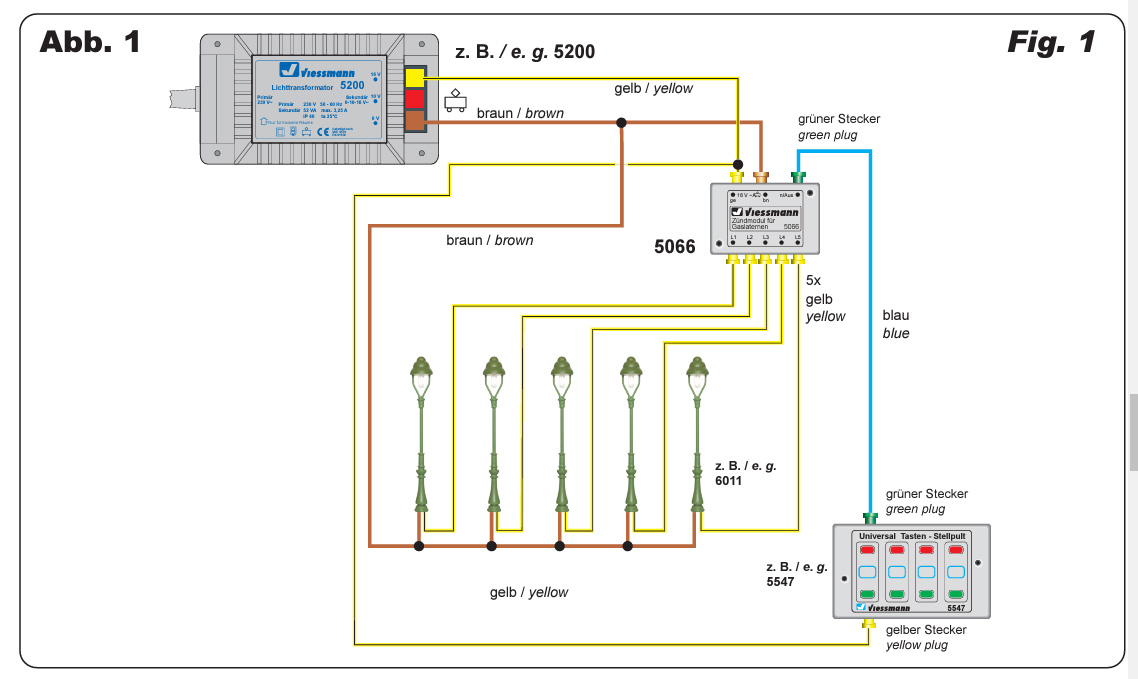
    Nothing like wiring everything up properly just to have it fail. After going through all the trouble of trouble shooting I discovered that the wiring schematic that came with the 5066 Ignition module was incorrect. Where it showed the brown wires going to each of the 5 ports it should have been the yellow wires (as seen in the correct schematic above).  Nothing going smoothly is par for course for this hobby I guess.

I decided against the Viessmann power supply (5200). It's overkill for my needs. So instead I ordered this basic 15 volt power supply. 

The power connector was installed with double sided mounting tape with a cable clip to secure the wires.

Plug it in and voila!  Now this is where the difference between incandescent and LEDs can be seen.  Incandescent on the left and LED on the right. I'm a big proponent of LEDs but the incandescents are performing much better here.  The LED is way too bright and doesn't have the range of brightness that the incandescent has. The incandescent does a great job of igniting and then glowing dim before slowly brightening as it warms up. Its final operating brightness is more realistic as well.  Plus the pool of light cast by the incandescent on the building and streets is much more pleasant than that cast by the LEDs.  Instructions come with the lamps on how to change the lightbulbs, so I might do that at some point.

But for now I am quite satisfied.

Yes sir!

Quite satisfied!

Dandy

Monday, November 23, 2020

Boulevard of Electric Dreams

Finally!  All 12 Electroliers are placed and wired.

After pouring a new rubber mold I concentrated on casting the remaining lamps once and for all.

Electrolier combination streetlamp/trolley line poles stand sentry on Grand Ave.
This whole scene is lit entirely by the Electroliers.


The remaining 8 Electroliers freshly cast and receiving their silver paint.

    For power supply I ordered this regulated 3 volt 2 amp transformer from Evan Designs. Its regulated so as to prevent voltage surges blowing out the LEDs (the LEDs are cast into the lamp, there is no changing them out!). The output voltage is exactly 3 volts and the 2 amps mean I can power up to 100 LEDs. That should be enough power for the streetlamps on all the streets. It also included a wired socket that I mounted underneath the layout for the power supply to plug into.


    All that remains to do now is install the span wires between the Electroliers to support the trolley wires. But the fact that the 3 volt dc lamps and 13.8 volts ac DCC both ground to the poles is of great concern for me. It would have worked fine when track power was DC. But since I switched to DCC which is AC, I'm not so sure. The last thing I want is a Boulevard of Broken Bulbs! So i'm going to rig up a test lamp/pole situation to try it out first so as to try to preserve this Boulevard of Electric Dreams.

Yes sir! This Boulevard of Electric Dreams!

Dandy

Monday, December 16, 2013

Operating System

Just a quick shot of the temporary control panel for the layout.

This simple set up is what I used while building the layout. I didn't want to invest any more money into the layout until I knew if it was going to work or not. So I used basic DC and a control panel built the old fashioned way:

Masonite cut to size.
Spray paint line color (cream).
Use tape to mask off route.
Spray paint main color (green).
Peel off tape revealing line color.
Drill for and install push buttons and indicator lights.
Dry transfers for street names.


These days its so much easier to build a control panel by designing one on a computer and simply printing it out and gluing it onto Masonite or Acrylic. Or, with the capabilities of DCC, a lot of folks are foregoing with control panels all together.


Electrical blocks are indicated (along with the direction of travel) by the gaps in the lines. So as you can see, this layout will eventually be able to accommodate a lot of cars!

These buttons control the NJ International switch machines. The switch machines have a bank of electrical tabs that power the indicator lights in the control panel. This has proven to be most troublesome and are the cause of almost all electrical shorts. Since the layout has proven itself and actually works, The NJ International switch machines are going to be replaced with servos which require a different type of switch. So like I said, this control panel is temporary. Yes sir. Its only temporary.

Dandy

Tuesday, June 18, 2013

Spaghetti Bowl

Wiring up Turnout Machines

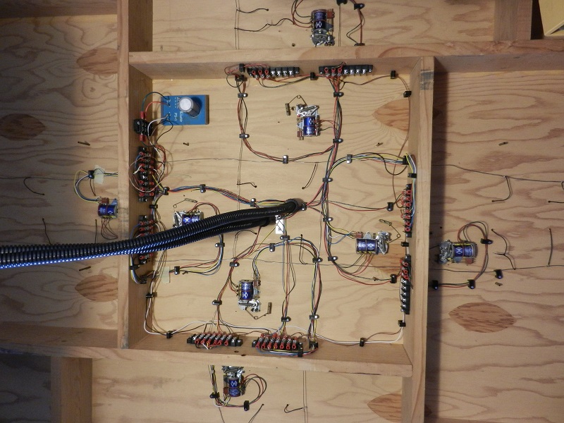
I installed these NJ International Turnout Machines years ago. But I find it very difficult to get the tabs for the control panel indication lights arranged just right so they don't short everything out. So I have foregone the indication lighting aspect of it for now and hooked them up to just switch the track. In the upper left is a Capacitive Discharge Unit from Miniatronics to give the turnouts a strong, decisive "snap"!

Eventually I would like to replace all the switch machines with easy to install and adjust micro servos.

The reason I haven't gone that route yet is because I don't want to invest another dollar into this layout until I see the intersection work as designed first! Yes sir! I want to see that intersection work as designed first!

Dandy