Transitioning the Layout to Automated Operation.
There doesn't seem to be any definitive how-to's when it comes to automating a layout. So I'm just going to figure it out as I go.
The first logical step seems to be Block Occupancy Detection. So let's start with that.
A couple of Digitrax BDL168 LocoNet Occupancy Detectors should work for this. Fortunately the track on the layout is already divided into electrical blocks from its DC cab control days. Later the blocks were "tied together" electrically when the layout was converted to DCC. Now I will "untie" the blocks electrically so that each block could then be wired individually to the BDL168's.
The control panel illustrates the location of the 32 detected blocks. Each block is labeled with a city block letter and sequence number. One BDL168 will detect 16 blocks, so two are required for this layout (How's that for a perfect fit!). The intersection itself is its own block and does not need to be detected.
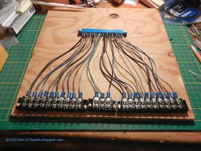
Rather than trying to wire the BDL168 while it's mounted under the layout, I temporarily mounted its 44 pin connector to a spare piece of plywood and wired it right there on the workbench. The other end of the wires are connected to terminal strips where the wires from the electrical blocks will be connected.
The wires had to be pre-tinned and then hammered into the shape of the holes they slide into.
Looking up underneath the layout (tap to enlarge photo). The 44 pin connector is mounted on the underside of the tabletop and the terminal strips are mounted to a joist with wires from the blocks routing in to the bottom row. The black and white wires on the far right are 14vDC (Digitrax PS14) power supply. The green wire in the center of all those wires is "ground" from the command station and the black wire next to it is the LocoNet connection. The BDL168 (green circuit board) is plugged in to the connector. LocoNet cables plug in at the far left, one to the command station and the other to the second BDL168. The rainbow ribbon cable is for RX4 Transponder detectors, which it turns out, are unnecessary since the computer keeps track of what cars are where, and, the decoders I'm using don't transpond! But I digress...
So I fired up the layout, some lights flashed on the BDL168's, and I ran some cars around as if nothing had changed. Which is good. It means power is going from the command station, through the BDL168's to all the blocks. But are the BDL168"s detecting? I won't know that until a computer interface is established so a computer program can read the LocoNet information.
So the next logical step seems to be establishing a computer interface with the layout.
Yes sir! Establish a computer interface!
Dandy


Loveely post
ReplyDelete