Thursday, November 15, 2007

Steaming Rig

The success of building a lighting valence in the configuration of a clerestory roof seems to be hinging on a big “if”. The roof curves from the front to the sides. And building this will require bending wood! The success of the valance hinges on if I can bend wood. Bend wood! Geez, that like goes against nature, bending wood.


I looked around the net and found some cool how-to videos on bending wood using steam. They're amazing. Oh I gotta bend wood. How cool would that be!


Roaming around a home improvement warehouse, I was able to MacGyver together an inexpensive steaming rig. I found some 3” flexible tubing that has a wide enough diameter to accept the 2” lumber that I'm going to need to bend.


Somehow, I need to attach that tubing to a big 'ol kettle that I will be using to boil water with on my stove. What I found was a roof jack. Roof jacks are used for rooftop vents. They have a flat base with a pipe coming off it. Because they are made for the pitched roof of a house, the pipe comes off the base at an angle. So when I lay the base over the kettle the pipe will angle away from the stove. That pipe has a 3”diameter, same as the tubing!


The tubing section had all sorts of attachments for these tubes, one of them being an insert to attach these tubes together. It fits perfectly in the roof jack pipe and the tubing, connecting them together.


Then I duct taped the heck out of the whole thing the keep it together and help keep the steam from leaking out.


Here you can see the kettle on the stove with the roof jack covering it. The black flexible tubing is attached to the roof jack with duct tape.


From the stove the tubing lays on a plank supported with a ladder.


Ah, look at it steam!

I went back to the store and got this cap that has a couple of holes drilled in it to try to keep more steam in the tube


In this shot you can see the 1/4” x 2” lumber inside getting steamed. The rule of thumb is about 20 minutes steaming per 1” thickness, but I ended up steaming them for a lot longer.


Next comes time to actually bend the wood, keep your fingers crossed! Yessir! Keep your fingers crossed!


Sunday, November 04, 2007

Display case frame

Oh what I wouldn’t give for a good basement! But, alas, basements are next to nonexistent in California. So, my layout currently resides in our dining room at the moment. And in an effort to keep our home looking nice, enclosing the layout in an attractive display case would be a good thing. A very good thing I think, how many homes have you ever walked into that instead of having a nice cityscape painting hanging on the wall, had an actual three dimensional miniature city with its lights twinkling away into the night? Personally, I think that would be way cool. The frame is now built. I used 1 ½” x ¾” and 2 ½ x ¾” to construct the four corner posts. A 2 ½” x ¾” connect two of the posts at the top to create a side assembly. And another matching side assembly is built in the same manner for the opposite side. These two sides are connected together with two more 2 ½” x ¾” using lag bolts and wing nuts to allow the unit to be broken down for transport.

Next comes building the clearstory roof which will require something I have never done before; bending wood around the corners. Yessir! Bending wood!

Monday, October 22, 2007

Display Case Gone Wild!

It all started off innocently enough. I needed to solve a problem. I need to keep the dang cats off of the layout. They’ve caused irreparable damage to the delicate overhead which means tearing it all out and rebuilding it. But I’m not going to rebuild until I have some way of preventing it from getting damaged again.

Covering it would be nice. Not only would it prevent the cats from terrorizing the good citizens of the city, but it would also keep the dust off. Doubly good!! A safe and clean city. Real estate values would sky rocket!

My wife suggested something like an acrylic cube, you know, like a display case in a museum. I think that to be a great idea, but I’m afraid the cube would be unwieldy and could actually cause damage to the city it was designed to protect when removing and replacing it.

Lightweight would be key. How about four posts holding up a wooden roof and removable acrylic panels would fit in the sides? Then the wooden roof could also have the lighting attached to it. Like a lighting valence! How about that? A safe, clean, well light lit city! Triply good!!!

When three problems are solved with one project, that’s a good hat trick. The project must be a good idea. I’m moving forward with it. So I’m gonna design the valence/display case.

What if instead of a standard rectangular valence, I kinda contour it like the clearstory roof of an old fashioned trolley? And instead of acrylic panels in the sides, I build it like the windows of an old fashioned trolley? The whole layout itself would look like an old fashioned trolley car! How kewl would that be?! Way kewl!

Could I really be able to build such a thing? I have no idea. I never built anything like it before. Should I build such a thing? Probably not. I’m sure there are all kinds of reasons why I shouldn’t. Am I really going to try and attempt it anyway? Knowing my history; yep, I'm affraid so. I’ll just take it one step at a time. Design a little. Build a little. Design a little more. Build a little more. Become frustrated and tear it all apart and replace it with something more practical. Well I hope I don’t have to tear it apart. Hopefully I’ll end up with something both practical and whimsical. Yessir, practical and whimsical!

Saturday, October 13, 2007

Smoke jack

Here you can see how I used the Dremel tool as a lathe to turn the smoke jack. I then drilled a hole in the roof and inserted the smoke jack.

Thursday, June 28, 2007

It's built!


Finally! It's built! Cartoon by my good friends at Project Firefly!

Welp, here it is. Entirely scratch built from brass stock.

Here you can see how I built up the roof end with 3 pieces of brass. Then I took the Dremel tool to it and ground it to the proper shape. One of the smoke jacks fell off. I’ll have to replace that.


The under carriage was fun one to build. The springs are brass spring wire that i wrapped around another wire. The wheels are built up tube stock while the spokes are cut from a single solid piece and then fit into the tires.


All that remains is to fashion some sort of harness apparatus for the horses.


So now it's off to the paint shop for a colorful eye catching paint scheme. Yessir! Colorful eye catching paint scheme!


Friday, March 09, 2007

Horsecar plans

As always- click the pic to enlarge!

Here is a page out of my sketchbook. I'm actually drawing these plans as I go along, thats why the page is so messy.

I'm taking measurements from the photos by assuming that the average size of a man at the turn of the 20th century was about 5” 8”. The drivers of the cars in both pictures are standing, so I can guesstimate the measurements of the whole car by using this assumption.

For the most part the car is boxy, which is easy enough to build. But there are a couple of places that will require a little modeling:

The sides curving in at the bottom will be a little tricky. But I think that if I use a thin gage brass here, and shape it to conform with the car ends, it ought to work out okay.

The wheels are unique with those spokes. Nothing is available commercially. But since this will be a static model, there is no need for them to have that “RP-25 contouring” to them. So I will just build them up using brass tube stock.

Roof ends- now here is the real stumbling block! They are a very organic shape- curving down to the front and the sides! I can't figure out how to do this. The only thing I can come up with is to take my Dremel Tool to a block of brass and grind away.

So there you have it. I'll post some pix of the car next time. In the meantime, I will keep grinding away. Yessir! Keep grinding away!

Thursday, February 22, 2007

Ancestry: Horsecars!

As if this layout isn’t historical enough, I have decided to add a little more history. For my next project I would like to model this San Diego horsecar. I know I should wait to finish the layout first before diving into such a project, but by building it now, I can pose it on the streets before the overhead goes in. That way I’ll have “before” and “after” pictures of the streets. This would give the impression of a successful horsecar line making the transition to that new fangled electrisical stuff. Pretty neat, huh? Yes-sir! Pretty neat indeed!
Other than the clearstory roof on the bottom car, these two cars are nearly identical. The top car has the window panels removed to take advantage of the nice weather, or at least to prevent it from becoming too stuffy inside form the heat. I will model it in this open configuration.

Thursday, February 08, 2007

Setting the bar too high?

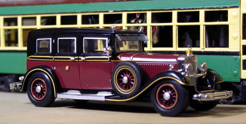
Okay, last automobile post for a while, then onto railroading. This is Ricko Rickos 1930-1938 Mercedes-Benz Typ770W07. I posed it in front of one of my San Diego 400 cars (which I’ll blog about later). Seeing the photo enlarged on my computer (click photo above to enlarge), I was shocked to see how the auto has far finer detail than the trolley itself! Notice the Mercedes logo (hood ornament) on the radiator cap. I didn’t even see it until I saw it in the photo- it’s so tiny! These are some dang nicely detailed auto models. There is no way I can match these standards! Yessir – no way!

Saturday, February 03, 2007

Motorcars on Parade


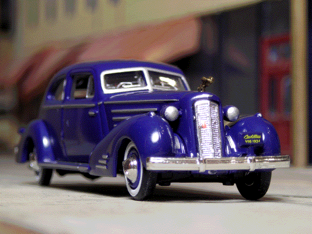
I really gotta get to work on the layout so I can get some progress photos for you! In the mean time, here is another auto for ya. This is Ricko Rickos 1934 Cadillac V16 Aerodynamic Coupe. Yessir- Aerodynamic!

Saturday, January 13, 2007

Happy New Year!


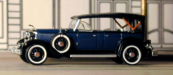
Welp, reading my last blog entry I find it interesting that I was making a big deal of the car models being “up to my standards”, when in fact the car models are probably setting the standards for my layout. And I just might be hard pressed to live up to these standards! I wouldn’t be surprised. Anyhowdy, here is another for ya. It’s a 1931Lincoln Model K. “K” for Kewl! If I keep to these standards, the layout should turn out pretty darn nice. Yessir, darn nice!

Thursday, December 28, 2006

Up To Standards!


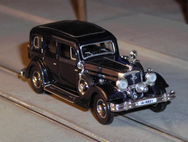
Merry Christmas all! I hope Santa was good to you. I must have been a good boy because that jolly ol’ elf brought me some of these automobile models by Ricko Ricko. These 1/87th “accurate scale model for adult collector” are superb! I am just thrilled by these. They are finely crafted and detailed and are definitely up to my railroads standards. The one pictured above is the 1935 “Horsh 851 Pullman”. And the $15.98 price tag is worth it to me especially since they are ready to go right out of the box. No assembly required (It’s a Christmas miracle)! These autos sharing the road with the streetcars are going to make for some wonderful traffic. Yessir, wonderful traffic!

Saturday, December 23, 2006

Inspiration


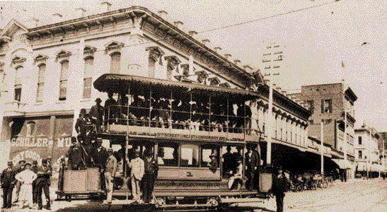
Here is a scene I would like to try to duplicate on the layout. It’s a historic photo of San Diego Electric #1 in front of the Backesto Block building on the opening day of the SDERy. The Backesto building still exists today and has been beautifully restored! So I’ll be able to take some measurements for the construction of the model. San Diego Electric #1 on the other hand....

Historical reenactment of this scene on the layout seems perfectly feasible to me. It could be built on the corner of 1890s and 1900s street. Notice how the trolley is rounding the corner instead of passing straight through the intersection, so that’s another plus. The stumbling block is the trolley itself. I would have to build that myself. But if I ever succeed at recreating this scene, oh what a happy day that will be, yessir, oh what a happy day!

Saturday, December 09, 2006

Simulating Girder Rail.

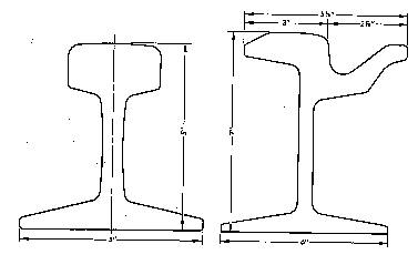
The prototype street railways use what’s known as girder rail to create the flangeway through the pavement. Here are cross section illustrations of standard “T” rail on the left, and girder rail on the right.

My plan is to simulate girder rail simply by laying two rails side-by-side to create the flangeways.

Thursday, November 30, 2006

Get Smart


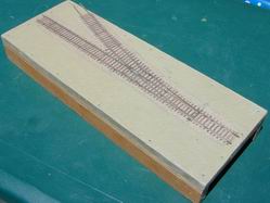
Girder rail, tight curves and sharp turnouts are typical with city trackage but not at all with commercially available model track. So it looks like I’m going to have to learn how to handlay all this myself. Fortunately for me, my local hobbyshop offered classes on hand laying track and turnouts for 5 bucks, so I jumped at the chance! Here is my graduation project.

Saturday, November 18, 2006

A Slice of Life


Big announcement: I don’t know what I’m doing! I’ve never built anything like this before. Do I build the streets first and then the sidewalks? Or vice versa? How do I create the flangeways in the pavement? Not to mention the nagging questions of whether the streets and sidewalks are wide enough. What’s a fellah to do?

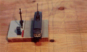
So I built this little test piece. Took a scrap piece of wood, laid some rail, paved in the streets and sidewalks, experimented with sidewalk and concrete colors. Added a wooden pole with some piano wire for overhead then added city details (streetlamp and phone booth.). Cool.

This has been a helpful little exercise. Yessir, a helpful little exercise!

Friday, November 10, 2006

The Future Site of San Dollar, Ca.

That’s what I’m calling the city, San Dollar. Not quite San Diego, but close enough.

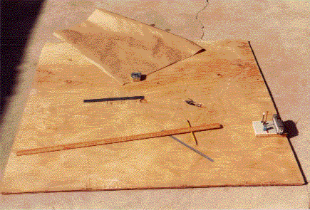
Well, I procured a piece of 3/8” real-estate. Cut it to 4’ x 4’, then drew the track plan, streets and sidewalks.

Now I’m getting an idea how big everything looks. I’m concerned that the remaining real estate for the buildings isn’t enough. The streets seem to be too narrow to accommodate automobile traffic as well. But if I widen the streets, the building real estate shrinks, and enlarging the real estate causes the streets to narrow! So, I’m trying to find the right balance. Further experimentation is required... Yessir, further experimintation!

Monday, October 23, 2006

Era

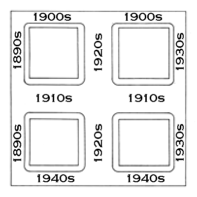
The Grand Poobah of model railroading, John Allen, built a 4 x 6 H.O. layout that eventually became the centerpiece of a basement empire. I have designed this layout so it too could be incorporated into a large layout. Problem is, I haven’t decided on the era as of yet. So I hit upon the idea that each street could represent a different decade. Then when the empire is designed, this little layout could be modified where needed to fit in.
In the meantime, It will be kind of fun to have each street a different era, showcasing the style and architecture of that decade. With 6 streets, the entire reign of the trolley can be represented (1890s to the 1940s) and the trolleys acting like little time machines, entering different decades with each corner they turn, you know, like a Hollywood backlot. Yessir, A Hollywood backlot!

Tuesday, October 03, 2006

Artist Concept Illustration


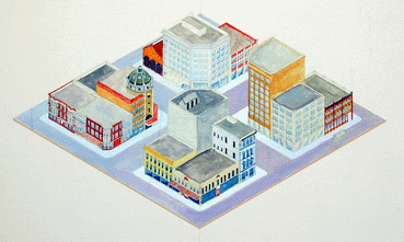
This illustration more accurately reflects the final design (The width of the streets and real estate). Recognize San Diego’s Gaslamp Quarter buildings? I’m pretty excited about this, it looks like it was lifted right out of a city!

Monday, September 25, 2006

Layout at a Glance and Concept Sketch

This is a concept sketch that I did to get an idea how the trolley layout would look. I wasn’t sure if it would look good because it has such an unusual track plan. I think it looks pretty cool, so I’ve proceeded with the final design.

Here are the stats for the trolley layout:

Layout at a glance:

Scale: H.O. (1:87.1)
Size: 4’-6” x 4’-6”
Theme: freelance, based on the San Diego Electric Ry.
Period: 1890s, 1900s, 1910s, 1920s, 1930s, 1940s.
Locale: freelance, San Diego’s Gaslamp Quarter.
Layout style: Tabletop.
Layout height:52”.
Benchwork: Grid.
Roadbed: Plywood.
Track: Handlaid code 80.
Minimum radius: 7”.
Maximum grade: none (level).
Scenery: Hydrocal (streets and sidewalks).
Control: Automated!