Wednesday, May 12, 2010

Valence Project ~ Light Fixtures

Hey! You know what this lighting valence needs? How about some lights!

I have been puzzling for some time now with how exactly I was going to install lights into this thing. I mean, lights are one of the major reasons for building this lighting valence in the first place after all.
One major stumbling block is that I'm not a certified electrician. The highest voltages I have ever dealt with is about 15VDC, you know, model railroad motors and whatnot. So its with some intrepidation that I design and build a 110V layout lighting system.

I'm interested in using the round bulbs that were popular with the old wooden streetcars and carousels during the early 20th century. But my walls and ceiling don't have space for wiring inside because, well, there isn't any inside. Just 1/2" plywood at best. I looked into using white, round bulbed Christmas lights. Just attach them to the ceiling and plug them in. Easy enough. But it just lacks that elegance I'm looking for. So I looked at how they were constructed and then headed off to the store to see what I could find.

 After MacGyvering my way through various home improvement stores, this is what I have come up with.

 I found a plastic candelabra cleat and the round bulbs that come in the candelabra size which is about the right size for this project. But the wiring is exposed, which doesn't seem like a good idea to me. So mounting the cleat directly to the valence out. I need some sort of housing for the cleat.

 A brass doorknob back plate! Looks like the stem of the cleat will slip right through the hole. But it didn't. I had to grind off about 1/16" with the Dremel tool. Then to close off the bottom... a sliding wardrobe door  brass pull! And here is how it all went together all nice and neat:
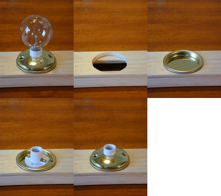
1. Wardrobe door pull. 2. Candelabra cleat. 3. Doorknob Back Plate. 4. Bulb.

The base is constructed of 2.5"x.25" trim wood and .75"x.75" angle trim from the moulding dept.
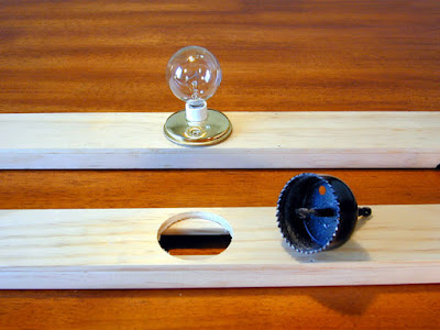
Then a hole was drilled to accommodate the light fixture.
Here is the completed lighting assemblies. The spacing of the bulbs coincide with the clerestory windows. Now all that's needed is wood treatment, staining and varnishing. And...


Wow! You would think I knew what I was doing or something. Now all that"s left is somehow wiring all this up in a safe and appealing way. But so far its looking just fine. Sure beats Christmas lights. Yes sir! Sure beats Christmas lights!

Dandy

Monday, April 19, 2010

Valence Project ~ Staining and Varnishing

You know, its funny. I started the Birney Project as a diversion from the ongoing lighting and anti-dust (and anti-cat) valence project. But that was so long ago now, and the Birney project has been so ongoing that working on the valence is now a divergence from working on the Birney!

So this is where I left off. With the major woodworking done, its now time to stain and varnish the inside.

Remember that this blog is not a "how-to" but rather a "how-I-did-it". Which isn't necessarily the best way. As it turns out, since I'm using a two-tone color scheme, the wood should have been stained ahead of construction. Masking doesn't work when it comes to staining. The masking tape will actually draw in the stain underneath it. And as you can see, I have quite a few spots where that happened. But overall it looks all right, doesn't it?

For the stain I used an oil based. Oils are harder to work with, but the results are so much nicer. For the main color I used "Natural", a stain that brings out the natural color of the wood. And for the trim I used "Golden Mahogany". Mainly because Mahogany was used as the trim for the old San Diego streetcars. Over all I'm pleased with the results. This valence is getting that elegant look I'm looking for. Yes sir! Quite elegant indeed!

Dandy

Sunday, March 28, 2010

Birney Project ~ Window Glass II

Cutting, shaping, and installing widow glazing.

In part one of installing window glass, some of the brass sills were filed away so that I could model some of the windows open. Now that the car is detailed and painted, the "glass" can be installed.

Really the glass is .015 clear styrene. Cut to approximate size, I held it against the window openings and marked the location of the sills with a sharp blade.

Then I scribed in the location of the openings in the styrene (bottom), checked it against the model, and then cut out the openings (top).

A reader of this blog suggested using Micro Kristal Klear for gluing in the windows. Its a water soluble product, so it doesn't craze (fog) the plastic the way petroleum based glue would. I found this to be really easy to use.
Finally, strip styrene matching the dimensions of the brass window sills was painted the trim color, cut to size and glued into place.
And there we have it! The open windows add a lot of character and realism helping to make this car a real one-of-a-kind model. Yes sir! A real one-of-a-kind model!

Dandy

Monday, March 15, 2010

Birney Project ~ A Weighty Situation

Adding Weight to the Birney Car 

The weights I used are those kind that you see that come in a long strip with double sided sticky tape on one side. They are usually divided into sections that can be broken off anywhere at 1/4oz increments. They are usually available at your local model train shop for weighting freight and passenger cars to NMRA standards. I was able to fit 4 of these 1/4oz weights for a total of 1oz added weight.

Location of weights
1. Cut and fitted to clear the motor frame and filed to conform to the curve of the end of the car. Then epoxied into place under the floor.
2. Trimmed to fit under the roof in the sub roof cutout.
3. Filed to conform to the curve of the end of the car. Then epoxied into place under the floor.

Weights 1 & 3 had their double sided sticky tape removed so that they can be slid under the pilot. There they were epoxied in place. Here you can see where weight #1 was trimmed to clear the motor mount.

Weight #4 had to be fitted inside the front of the car. Yes, the car has a "front and rear" now. Originally it was designed to be double ended, but I ran into this problem. As you can see, Birney the motorman has been removed from the seat assemblies and is now fitted into the front of the car.
Weight #4 was notched to fit around Birney the motorman's seat.

The top of the weight had to be ground out to clear the headlight bulb and wires. Then it was painted black and glued into place.

After all that effort I was able to add an additional 1oz to the car bringing it to a total of just over 5oz. Doesn't sound like much but that is another 25% added to its weight. And the car is suprisingly heavy when you pick it up. Yes sir! Quiet heavy.

Dandy

Wednesday, March 10, 2010

Birney Project ~ Phun With Fysics

 After a test run on the Southern California Traction Clubs city modules, the drawbacks of single truck trolleys became apparent on ol' 301.

Sir Lord Dr. Isaac Nudeton Esq III PHD.

Nudeton's 3rd law of force states: "The force of the trolley pole pressing up against the overhead contact wire is equal and opposite to the force pressing down on the trolley car.". Who knew Nudeton was a trolley fan!
Well that force was evident on the Birney car. The pole pressing down on the back of the car coupled with the fact that there is a weight behind the decoder puts more force on the back wheels than the front wheels. So the back wheels become in effect, a fulcrum. In other words, the trolley wants to do a wheely.

And a trolley that wants to do a wheely doesn't want to take curves, it wants to keep going straight.

So the solution is: More weight in the front of the model, get those front wheels down so that the flanges will help the trolley get around corners.

So after making the bold statement of "There is officially no more room for anything else in this model!", I have to find more room for more weight in the front of the model. Yes sir! Have to find more room!

Dandy

Monday, February 15, 2010

The Model Railcast Show

A Model Railroad Focused Podcast

Packed full of interesting and useful information, I have been listing to The Model Railcast Show podcast for over a year now. I think its here to stay.


The price can't be beat ('tis free), and is published about weekly. And its perfect to have on in the background while working on the railroad (or in my case, while working at work).
The show is hosted by a fun cast of characters, Ryan is an absolute noob, but he is learning fast. And Tim Harrison seems to be a little more advanced. Their guests are all heavy hitters in the model railroad industry, from manufacturers like Duncan McRee of Tam Valley Depot, industry professionals such as former MR Staff writter Marty McGuirk, to basement empire builders like Don Ball and Craig Bisgeier. And the best part is, all these guys are available on the discussion forums on the Model Podcast website for further comment, any clarifications and whatnot.

It doesn't matter what your experience with model railroading is. The podcast is "for railroading beginners and seasoned line veterans" alike.

So give it a listen. I'm sure you won't be disappointed. No sir! You won't be disappointed!

Dandy

Sunday, January 31, 2010

Birney Project ~ Installing the Decoder

"You've got too many damn lights in that thing!" George Huckaby.

I may have blown out all my lights, but the Southern California Traction Club has blown out entire decoders trying to get these things to work properly in trolleys running under live overhead! As a grateful benefactor of the trials and tribulations that the SCTC went through, I drew the following schematic based on the findings of the club (clicky to make biggy) :

This schematic illustrates how the TCS M1 decoder is to be wired in my model of SDERy Birney #301. The model has 10 (yes 10!) incandescent light bulbs in it, five of which would be lit at any one time (If I had to do it again, I would rather use LEDs in conjunction with fiber optics). The schematic also includes the necessary resistor that was so agonizingly missed the first time. I have the choice of having one 1 watt 100 ohm resistor* on the white wire and another on the yellow wire. Or one big 2 watt 100 ohm resistor* on the blue wire. Considering how big the resistors are (they are bigger than the decoder!) and how hot they get (and they get hot!), I decided to go with the one big resistor. BUT! That means not all the lights can be lit at the same time! Or else "poof"! Out go the lights yet again! That's a disaster waiting to happen, I'm going to have to be damn careful. Yes sir, Damn careful.
* Note: The value of the resistors were determined by some of the club members using wizardry and gadgetry that I'm not familiar with.
Bonus! Check out the March 2010 issue of Model Railroader for a resistor selector device on page 26.

First, the decoder is mounted to a piece of 3M 4011 Double-sided Mounting Tape, which in turn is mounted to the ceiling of the model.


Then comes the surgery. Two wires from 10 bulbs = 20 wires, plus 7 from the decoder, plus two from the motor, and two from the connector. Let's see, that's... 31 wires that all have to make specific connections with each other and the resistor, all in an itty bitty living space!


In this photo, we're looking through the cutout in the floor to the cutout in the subroof. I'm trying to keep the decoder (which also gets hot) as far away from the hot resistor as possible. So the decoder(right) is mounted to the roof through the subroof cutout. On the left side of the cutout I mounted a weight (simply for better running). The resistor (left) is glued half on the subroof and half on the weight. Hopefully this will help dissipate all that heat. There is officially no more room for anything else in this model!

Everything tucked up into the ceiling pretty nicely, preserving the seethroughableness of the car, even at this low angle. Good enough for me. Next stop will be the programing track to program the decoder. Then I'll officially take my place among the ranks of DCC-ers. Yes sir! I'm getting with the program!

Dandy

Monday, January 25, 2010

Birney Project ~ Going DCC

Taking the plunge into the world of Digital Command Control!

Having been a model railroader my whole life, its about time I made the switch from DC to DCC. Since my layout was designed for automatic operation, it was built with DC block control. But features with DCC have convinced me that this is the way to go. So starting with this Birney project, I'm making the switch.

For the Birney I've decided to use the M1 decoder from TCS (Train Control Systems). The M1 decoder is designed for N scale but fully capable of running H.O.

Programs are available now that allow you to run your layout from your laptop. One of these programs coupled with this decoder and I can have the automated layout as originally conceived.

How about that! For once I can have my cake and eat it to. Yes sir! I can have my cake and eat it too!

Dandy

Monday, December 28, 2009

Seasons Greetings!...

...and a happy strands of LEDs on sale for cheap for all your modeling lighting needs time of year!

I picked up a strand of 70 warm white LED's for like $5. That's less than 8 cents per LED!


Dandy

Monday, November 30, 2009

Tour the Southern California Traction Club

The SCTC displayed it's HO trolley modules setup at the NMRA L.A. Division meet at the South Coast Botanical Garden in Palos Verdes CA a couple weeks ago. This is my first show with the club. I pretty much spent the entire time video taping the layout in action, amassing about an hours worth of video. I was able to distill that video down to about 8 minutes for your viewing pleasure:


The Southern California Traction Club modules feature spectacular cityscapes, fully detailed scenes, long mainline running, multiple trolleys operating from live overhead, and a whole lot more. So sit back and enjoy the ride. Yes sir! Enjoy the ride!

Dandy

Monday, November 23, 2009

Niles Project ~ Headlight and Retrievers

Apparently, in the early days of trolleys, headlights were not standard equipment.

Since nighttime photographs were difficult and therefore rare, no photographs in my collection depict any of the Niles cars with headlights. For years I figured that either the cars didn't run at night, or they ran without headlights. But studying my collection closer reveals:

1. A bracket. And some wear and tear just above it. It could very well have been a headlight bracket and that it was often used.

2. A builders illustration including a headlight. It also depicts how the headlight sits low and rests on the front bumper (?).

3. Historical conformation of just such an arrangement. Pacific Electric 1001, which still exists today, sports a same sort headlamp. It fits onto a braket and you can see how a cord extends from it and has to be plugged in.

Precision Scale Co. Incandescent Headlamp For Interurban Cars #31004 seems to fit the bill quite nicely. The sprue on the back has to be cut off and then I filed the back for a good fit on the car. While I'm at it, I'll add the retriever fabricated from a 3/64" brass rod.

So now we are good to go with some night time running. Yes sir! We're good to go!

Dandy

Tuesday, November 17, 2009

Birney Project ~ Boom! Boom! Out go the lights!

Dammit! My worst fear has come to pass. I blew out all the light bulbs. F!

Deciding to take the plunge into the world of DCC, I managed to blow out all 10 light bulbs. I thought it was going to be a simple matter of replacing the Utah Pacific Constant Lighting Unit with a decoder. But no. Apparently a resistor is needed between the bulbs and decoder. The total rating of the bulbs have to be under 100 millowatts and how bright the lights shine depends on the resistor. The size resistor needed can be determined from the website of the manufacturer of the decoder, but not on the instructions that come with the decoder. I didn't know that so... pffft! Blown bulbs.

This disaster blew the wind out of my sails. I focused on other aspects of life for a while. Then, after a sufficient time of pouting, I'm back. Birney has been disassembled, blown bulbs ripped out, and new bulbs installed.

Sorry about the lack of posts for a while, but I'm back on track now. Yes sir! Back on track!

Dandy

Monday, October 19, 2009

Birney Project ~ Hold Down Hooks

Fabricating New Trolley Pole Hold Down Hooks For The Birney.

Trolley poles pointing downward is a bad thing. The hold down hooks are too short. So I'm going to fabricate some new hooks that are taller and more prototypically correct.


Using a cutoff disk on a Dremel, I cut off the old hooks.

Since the trolley poles are wired to the leads of the motor, the hooks need to conduct electricity from the brass body of the car to the pole. So I had to remove paint from where the hooks will be soldered to the car.

To fabricate the hold down hooks, I started with .010" x .030" brass bar stock folded in half.

Using a nail (I found a nail that was the same diameter of the old hook loop) I looped the brass around getting a nice curve by using pliers and a screwdriver to work the brass into shape.

Add a reverse curve in the brass so that the apex of the loop is in line with the main shaft of the hook. Solder only the loop, the reverse curve and part of the neck together.

Then bend the legs out and fold in the feet that will be soldered to the base. The hook assembly is now done.

Solder the hook assembly to the roof boards and trim the feet. Give it a tug to confirm a good connection. Now its time to paint the hooks and while I'm at it, I'm going to right a wrong...
Roof boards were never the same color as the roof. Roofs were usually of canvas or thin sheet metal, so you don't want to step on it or you'll fall right through or bend the heck out of it. So roof boards were installed so that workmen maintaining the cars could stand on the roof without damaging it. They were usually made of wood and were painted a contrasting color so the workmen could see where to step out of their peripheral vision. My hands are pretty steady, but not at this tiny scale. So I masked off around the boards.
Brushed on some Scalecoat Roof Brown on the boards and painted the hooks black. Some weathering will kill the shine on the boards.

Now that's more like it! The car looks much better and the horizontal poles are getting a much better electrical contact with the hooks now. Storing the car with poles on help keep the connection from oxidizing. Got to do everything you can to keep good electrical connections throughout if you want to keep them doggies rollin'. Yes sir! Keep them doggies rollin'!

Dandy