Monday, October 26, 2020

BDL168's ~The Robots Are Taking Over Our Jobs!

 Transitioning the Layout to Automated Operation.


    There doesn't seem to be any definitive how-to's when it comes to automating a layout. So I'm just going to figure it out as I go.


The first logical step seems to be Block Occupancy Detection. So let's start with that.

     A couple of Digitrax BDL168 LocoNet Occupancy Detectors should work for this.  Fortunately the track on the layout is already divided into electrical blocks from its DC cab control days. Later the blocks were "tied together" electrically when the layout was converted to DCC. Now I will "untie" the blocks electrically so that each block could then be wired individually to the BDL168's.


The control panel  illustrates the location of the 32 detected blocks. Each block is labeled with a city block letter and sequence number. One BDL168 will detect 16 blocks, so two are required for this layout (How's that for a perfect fit!). The intersection itself is its own block and does not need to be detected.


Rather than trying to wire the BDL168 while it's mounted under the layout, I temporarily mounted its 44 pin connector to a spare piece of plywood and wired it right there on the workbench. The other end of the wires are connected to terminal strips where the wires from the electrical blocks will be connected.

The wires had to be pre-tinned and then hammered into the shape of the holes they slide into.


Looking up underneath the layout (tap to enlarge photo). The 44 pin connector is mounted on the underside of the tabletop and the terminal strips are mounted to a joist with wires from the blocks routing in to the bottom row. The black and white wires on the far right are 14vDC (Digitrax PS14) power supply. The green wire in the center of all those wires is "ground" from the command station and the black wire next to it is the LocoNet connection.  The BDL168 (green circuit board) is plugged in to the connector. LocoNet cables plug in at the far left, one to the command station and the other to the second BDL168. The rainbow ribbon cable is for RX4 Transponder detectors, which it turns out, are unnecessary since the computer keeps track of what cars are where, and, the decoders I'm using don't transpond! But I digress...


So I fired up the layout, some lights flashed on the BDL168's, and I ran some cars around as if nothing had changed. Which is good. It means power is going from the command station, through the BDL168's to all the blocks. But are the BDL168"s detecting? I won't know that until a computer interface is established so a computer program can read the LocoNet information.

So the next logical step seems to be establishing a computer interface with the layout.

Yes sir! Establish a computer interface!

Dandy

Thursday, October 01, 2020

The Real № 9 in Action

Old Photo of № 9 Making Its Way Down 5th Street.


or it could be #10, I can't make out a number. ca1890

But I can make out that I put the headlight in the wrong place. This photo shows it on the roof. I wish I had seen this photo sooner. Installing the headlight on the roof would have been so much easier!

Yes sir! It would have been so much easier!

Dandy

Monday, September 14, 2020

№ 9 ~ Guiding Light

 Adding Headlights

The prototype didn't have headlights but on models the headlights are a great way to determine if the car is communicating with the DCC command station without having to run the car out of the carhouse. And since this model has a headlight casting on it, I might as well add headlights.

I should have done this before I painted the car. But the decoder has all these features for directional headlights, so I might as well use them.


Tiny LEDs. I picked up these 1.8mm/2mm LEDs online. I had to trim the leads very short to get it to fit on the car. The body of the LED is painted black so that only the "bulb" lit up.


Black Blob. Soldering the wires to the short leads proved to be tricky. I burnt one LED attempting this. But using a needle nose pliers as a heat sink helped. Then I slathered the whole thing with Liquid Electrical Tape to prevent shorting.  Yes sir! "Slathered"!

Routing the wires from the LEDs down through holes drilled in the floor, superglued along the bottom of the floor, then routed up inside the car to where the decoder will be.

A blop of Micro Kristal Klear for the headlight lens.


"Happiness can be found
even in the darkest of times,
if one only remembers to
turn on the light."

Albus Dumbledore

Yes sir! Remember to turn on the light!

Dandy

Monday, August 31, 2020

№ 9 ~ Official Portrait

The San Diego Electric Railway opened with great fanfare on September 21st 1892!

But by the time № 9 stopped for its photo much of the fanfare had moved on leaving one official, two patrons, a motorman, and a conductor to pose with it.


San Diego Electric Railway № 9

This marks the first time I've photographed a completed scene on my layout. Finally! But the layout is far from complete.

Here's the set up. Pretty simple.

Some people model historic battle scenes, some people model fantastic sci-fi scenes, I model everyday life of old San Diego. What does that say about me? I don't know. But if you know, don't tell me- I don't want to know.


Yes Sir! I don't want to know.

Dandy

Monday, August 17, 2020

№ 9 ~ Cast and Crew

Painting Up Some Folks to Populate Ol' № 9.

The Usual Suspects

These pewter figures by Andrew C. Stadden are beautifully sculpted, highly detailed, and very much in scale and proportion. They don't come painted though, so I'm going to have to make my first foray into doing that.

I glued them to blocks of wood to help make the painting process easier. First I spray primed them and then painted them by hand. There are plenty of videos on YouTube about painting figures that I watched before I started so I would have a pretty good idea of what I was getting into. This guy did a live stream of painting a Preiser figure in real time that helped a lot.

I chose figures that came closest to looking like these guys in this 1892 photo. I thought I would photograph a "reenactment" of this scene with my models.

Yes Sir! A reenactment!

Dandy

Sunday, July 19, 2020

Good Oldie Moldie

A New Rubber Mold for the Electroliers.

The Electrolier/Line Pole Project is back on track with a new mold after the last mold failed.


This time I went with a more durable silicone rubber:

Smooth-On Mold Star. It only cost a couple bucks more but its supposed to produce a stronger mold. So we'll see.

So to recap, four useable lamps done when we last left off, and now 8 lamps to go.

Yes Sir! 8 to go!

Dandy

Monday, June 29, 2020

№ 9 ~ Going for a Drive

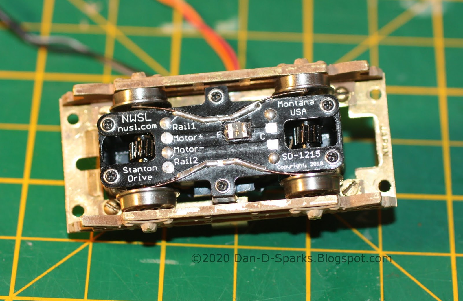
A NWSL Stanton Drive that is.

     In a previous post I had mentioned that motoring this trolley would be the stumbling block for this project. But a Dan D. Sparks Blogspot reader Don Ball had commented that he has had luck with the  NWSL’s new DCC-ready, self-contained underfloor power unit. So after looking in to it I've decided to order one and give it a go.

A quick look, it looks like it should fit (somehow):

Specs:
H.O. Scale NWSL Stanton Drive Model 1215
8'0" Wheelbase
33"/110 Wheels

The 33" wheels are the smallest that NWSL offer. The original wheels on the model are 28". So I had to give a little there.
I also went with the 110 wheel width. Four wheel cars notoriously ride rough, model or prototype. So the wider wheel width should help the car successfully navigate the intersection every time.


Just barely fits! Couldn't be any bigger. The corners of the Stanton almost touch the four screws holding on the side frames. If it was any bigger I would have had to find a different way of attaching the side frames.

The original floor had to be opened a bit to fit the Stanton. I was able to keep the original weight in place. A motor mount was fabricated for the Stanton to screw onto and hold it at the proper height.

An important thing to note is that the Stanton is not symmetrical in length. The housing was designed for two different wheel base sizes (probably 8'0" and 8'6" in this case). I have the smaller size so one of the wheel sets is closer to the pivot than the other. So Note to Self: The motor mounts one way (wires opposite side of pivot from the weight).

It's in there! What was once a formidable task is now in the past. Relief. Now it's time to move forward. Next: Decoder and a Pole.

Yes Sir! Keep moving forward!

Dandy

Monday, June 22, 2020

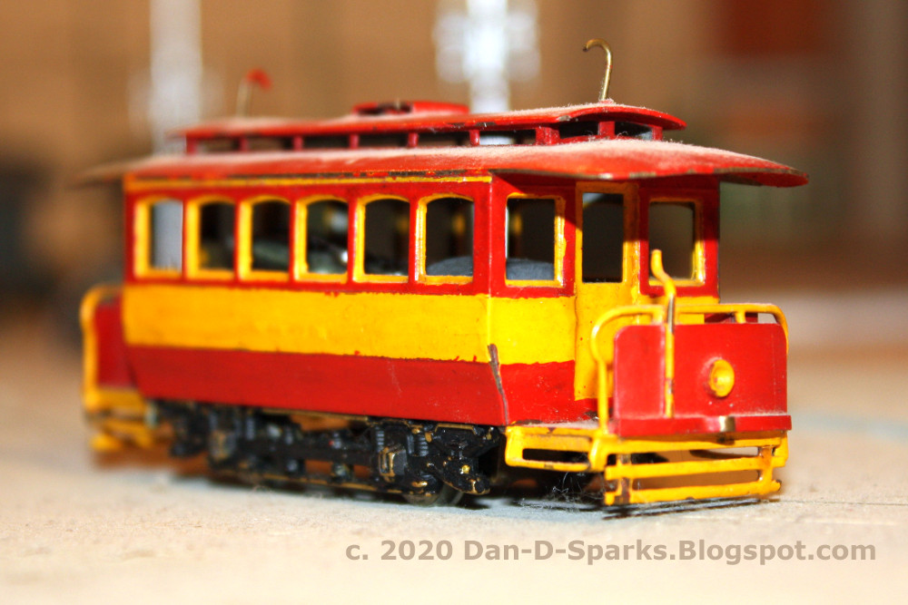
№ 9 ~ Decaled

Pinstripes and Neat Lettering Sure Add A Lot of Elegance to a Car.


For all those building their own SDERy #9, I make available to you the decal artwork. Click for the hi-rez version:


Well I'm pleased with how well its going with this car. So I have decided to press on with bringing it to fully operational completion. The next step is to see if I can fit a decent motor in it. Don Ball suggested a NWSL Stanton Drive for it, so I'm going to look in to that.

Yes Sir! Elegant!

Dandy

Monday, May 18, 2020

№ 9 ~ Straight Outta Paintshop

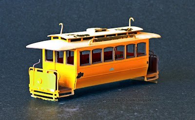
№ 9 Gets A Fresh Coat of Yellow and Brown Paint.

TruColor Reefer Yellow for the body color, Roof Brown for the trim, Foundation for the roof and trucks.

But first, the brass was cleaned and primered with TruColor Light Primer (to help the yellow show up).

After the interior and body were painted, I masked the whole thing except for the window frames and platform for the TruColor Roof Brown. 

Yikes! A lot of paint pulled off with the unmasking! Either: TruColor is a delicate paint, or I didn't wait long enough for the paint to cure (24 hours), or I should have sprayed a sealer coat on first. Anyway, touch ups required.

But, the whole reason for this exercise, what initiated this project in the first place, was to try out TruColor Reefer Yellow as SDERy Yellow. And you know, its pretty darn close if it doesn't actually nail it!

Yes Sir! Might of nailed it!

Dandy

Monday, May 04, 2020

LMB Old Time Trolley

Sizing up an Old Model to Rebuild into SDERy #9

Last post I determined which cars I'm going to use for my fleet. But as I was retrieving them from my collection I came across this old Old Time Trolley "basketcase" model I purchased from George Jones. My first thought was to try out some Tru-Color Reefer Yellow on it to see if its a good color to represent SDERy Mission Yellow. But the more I look at this car...

 
I believe this is be an old LMB "Open End Trolley" model from c1961.

The model is very similar in appearance to SDERy #9 and #10.

Built by Brill in 1892, #9 and #10 ran for 17 years before they were retired in 1909.


A side-by-side comparison reveals that the windows on the model are too short as well as is the roof. Other than that though its pretty darn close.  I think that the model captures the feeling of the prototype quite well.

So into the Pine-Sol bath it went to strip it of paint.

I also fabricated route signs for the sides of the roof.

I guess I'm moving forward with this project! But I'm not sure how far I'm going to be able to get with it, motoring this model seems to be a stumbling point. But so far I'm committed to painting and decaling it. After that, we'll see where this goes

Yes Sir! We'll see where this goes!

Dandy


Monday, April 27, 2020

Determining the Content of the Fleet

This is part 2 of the "Determining the Basic Fleet Series". In part 1 I estimated that 16 cars would be required to fill the layout. Now the question is:


Just Which 16 Cars Should I Model Anyway?


Browsing though the history books of the San Diego Electric Railway and seeing the variety of cars, it is so easy to just want them all!

But that's not practical.

So what is practical? Build models that are commercially available now. Scratch build later.

So using that parameter, here is my breakdown of the 16 cars:


QTY
Make
Model
3
Pacific Traction
400 Series Class 5
3
Andrew Chier
Unannounced project
3
Bachmann
Birney
3
Suydam
Niles
3
TBD
PCC
1
NJ Custom/Orion
3rd Ave Railway 400 Series

Suydam Niles, Pacific Traction 400, WP PCC, Orion 3rd Ave Car, Ken Kidder Birney

You know, seeing this list, suddenly building a fleet doesn't seem like too huge of a project. 
This actually feels downright doable.

Yes Sir! Downright doable!

Dandy


Wednesday, April 22, 2020

Estimating the Size of the Fleet

Just How Many Cars Are Required To Populate This Layout Anyway?


Considering the time and expense that goes into completing just one single car, I would like to focus on building a basic fleet.

Suydam Niles, Pacific Traction 400, WP PCC, 3rd Ave Car, Ken Kidder Birney

The Maths:


The layout is designed for automated operation. Given that there are 4 city blocks each divided into 8 detection blocks, this makes for a total 32 detection blocks (the main intersection is the 33rd block and is undetected- once a car is cleared to enter the intersection it does not stop.).


I estimate that for maximum traffic and yet smooth operation* only half the 32 blocks should be occupied by a car. That way generally each car has an empty block ahead of it. 

So a car on every other detected block makes for 16 cars.


The Answer:


16 cars:  motored, poled, painted, decaled, decodered, and detailed, to make for a maximum traffic operating session (though it might be fun to add that 17th car to see what happens with congestion ;) ).

Yes Sir! It might be fun!

Dandy


* Theoretically, the layout could "run" a maximum of 31 cars, but only one car would be moving at any given time. Basically it would be moving that one empty block around the layout.

Monday, September 26, 2016

New Auxiliary Control Panel

A Quick and Dirty Control Panel for the New DCC Turnout Controls.

The old DC NJ International Turnout Machines are being replaced by Tam Valley Depot Singlet DCC Decoder and Servo Drivers. So as a result a new control panel is required for the Fascia Decoders.

Control Panels are way easier to make these days with a computer and printer compared to the old mask and paint method.

This new panel is drawn with the free vector graphics program Inkscape. This time I included labeling for the electrical isolated blocks as well as a letter designation for each of the four city blocks.

The drawing was then printed out and glued to 1/8" Masonite Board. And then drilled to accommodate the Servo Decoders. Done! Easy peasy. Well... except now comes the wiring!


This new auxiliary panel provides a manual way to control the turnouts since primary control of the layout will be controlled by the computer. But I know computers, and my experience with computers has taught me that a manual alternative would be a wise thing. Yes sir! A wise alternative!

Dandy

Thursday, March 10, 2016

Track ~ Electrically Isolated Blocks

DC Block Control, Eliminated, and then Revived...

Gaps in the rails.  Originally designed for DC Block Control, DCC eliminated the need for these electrically isolated track blocks.

Power bus. A bare wire is run under the layout following the cloverleaf pattern of the track above to tie all the block wiring together.

Block Detection for Automation. Putting those old blocks to good use, they can be used to give feedback to loconet for use in running the layout automatically or semi-automatically.

Yes Sir! Running the layout automatically!

Dandy

Monday, February 01, 2016

TCS Keep Alive DCC Decoders

Installing A DCC Decoder In A Poor Running Model Yields Surprising Results!

One of the advantages touted by DCC proponents is that it improves the performance of motors. So I decided to add a TCS Keep Alive Decoder to my poorest running model to see how it fares:

A Huntington Standard by Oriental Models.
It features a crappy open-frame motor and all brass gears ( usually alternating brass gears with plastic gears produce much better performance).

And wouldn't you know it, I was able to get decent performance out of it. In this short video I was able to run the car around the block with some realism:


Yes sir! Decent performance!

Dandy


Tuesday, January 05, 2016

Digi for the Trax

Santa Baby Was Good To Me!

Digitrax DCS 51

It's official, the layout has gone digital. Though DC was fun, playing keep-away by only using the turnouts...:


...but it's time to start implementing realistic operation. So DCC it is!

To make a quick connect/disconnect between the command station and layout I purchased these XLR Connectors. They seem able to handle any maximum amperage the command station should dish out.

Under the layout shot. The female XLR Connector was mounted to a small project box and then wired to the layout. The male in-line XLR Connector was wired to a 16awg 3 conductor cord (positive, negative, neutral) which is wired to the Command Station.

.We are now DCC ready. Yes sir! DCC ready!

Dandy

Tuesday, December 08, 2015

Oh No! The Rubber Broke!

Apparently, Rubber molds have a shelf life.


Half way through the casting of the street lamps needed for Grand Ave, the rubber mold decides to completely fail.

Now it could be I didn't use enough release agent. But the mold also cracked (Maybe the sun got to it? UV rays are so destructive!). So I'm sure its at the end of its shelf life.

So the next time I make a mold, I have got to make all the casting right away.
Yes sir- Right away!

Dandy